Use A Continuous Cooling Transformation Diagram For A Chegg

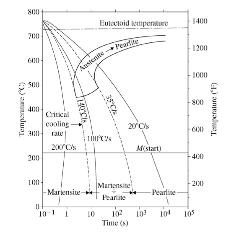
Use A Continuous Cooling Transformation Diagram For A Chegg Here’s the best way to solve it. 2. use a continuous cooling transformation diagram for a carbon steel of eutectoid composition and identify the microstructure found after cooling properly equilibrated austenite at the following rates: 20°c s 6. 100°c s . 200°c s. 800 l eutectoid temperature 1400 700 pearlite 600 3 austenite temperature. Question: use a continuous cooling transformation diagram for a carbon steel of eutectoid composition and identify the microstructure found after cooling properly equilibrated austenite at the following rates: a 20c s b 100c s c 200c s.

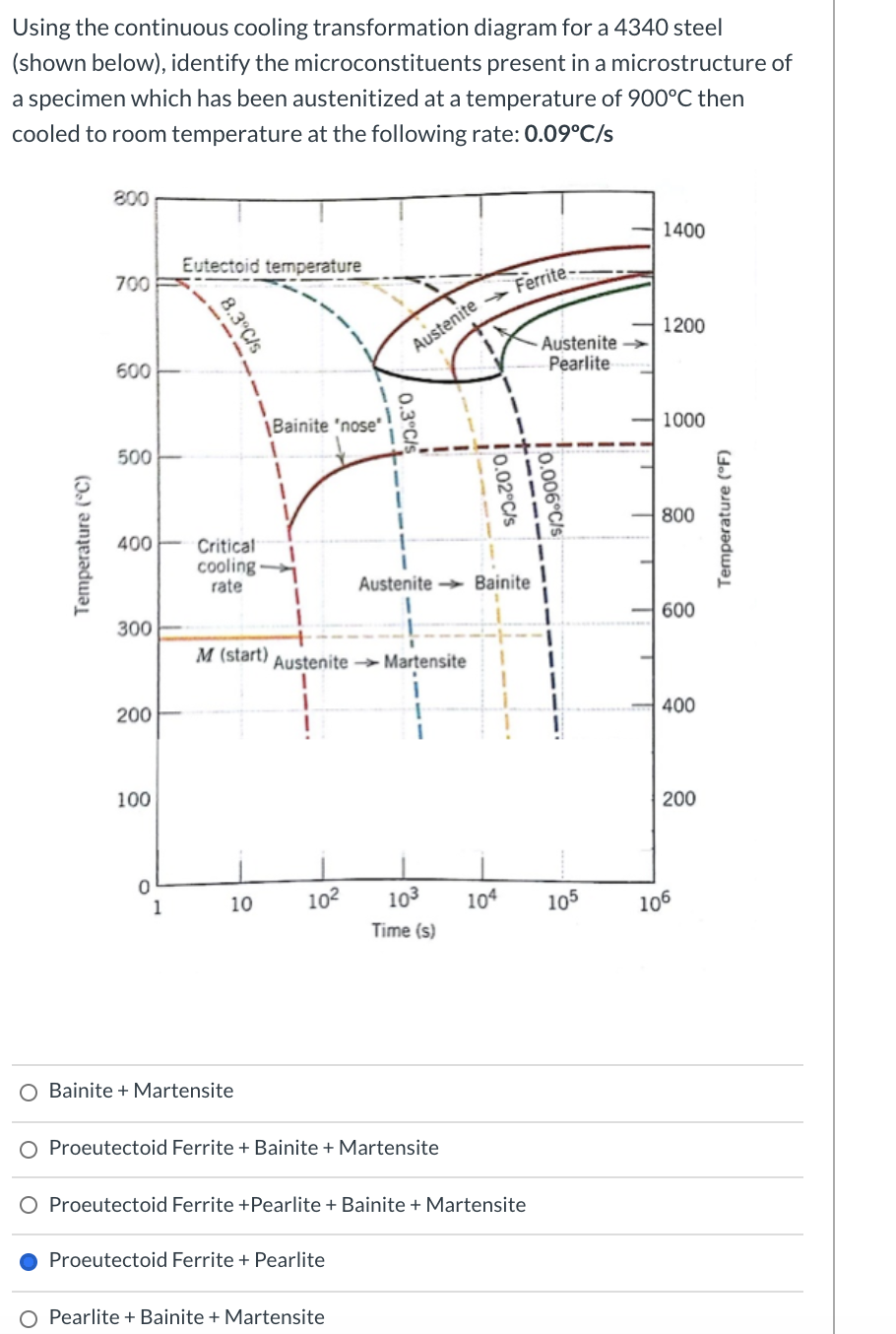
Solved Using The Continuous Cooling Transformation Diagram Chegg Question: using the continuous cooling transformation diagram for a 4340 steel (shown below), identify the microconstituents present in a microstructure of a specimen which has been austenitized at a temperature of 900ºc then cooled to room temperature at the following rate: 2ºc s. there are 2 steps to solve this one. Using the continuous cooling transformation diagram for an iron carbon alloy of eutectoid composition, figure 10.28, name the microstructural products of specimens having this eutectoid compositions that are first completely transformed to austenite, then cooled to room temperature at the following rates: 175°c s: 90°c s: 15°c s:. Definition: stability of phases during continuous cooling of austenite. there are two types of cct diagrams. i) plot of (for each type of transformation) transformation start, specific fraction of transformation and transformation finish temperature against transformation time on each cooling curve. A continuous cooling transformation ( cct) phase diagram is often used when heat treating steel. [ 1] these diagrams are used to represent which types of phase changes will occur in a material as it is cooled at different rates. these diagrams are often more useful than time temperature transformation diagrams because it is more convenient to.

Solved Using The Continuous Cooling Transformation Diagram Chegg Definition: stability of phases during continuous cooling of austenite. there are two types of cct diagrams. i) plot of (for each type of transformation) transformation start, specific fraction of transformation and transformation finish temperature against transformation time on each cooling curve. A continuous cooling transformation ( cct) phase diagram is often used when heat treating steel. [ 1] these diagrams are used to represent which types of phase changes will occur in a material as it is cooled at different rates. these diagrams are often more useful than time temperature transformation diagrams because it is more convenient to. Isothermal transformation diagram • the iron carbon system is very significant for industrial applications, and has been widely studied. • the formation of pearlite from austenite has been extensively investigated under both isothermal transformation and continuous cooling conditions – isothermal transformation: samples are held at. Typical continuous cooling transformation diagrams using this method are shown in [1]. these diagrams allow the prediction of hardness and microstructure in the center of any diameter bar. this is also the most common method for displaying cct diagrams. figure 1: cct diagram for aisi 1060 steel. figure 2: cct diagram for aisi 5160 steel.

Comments are closed.