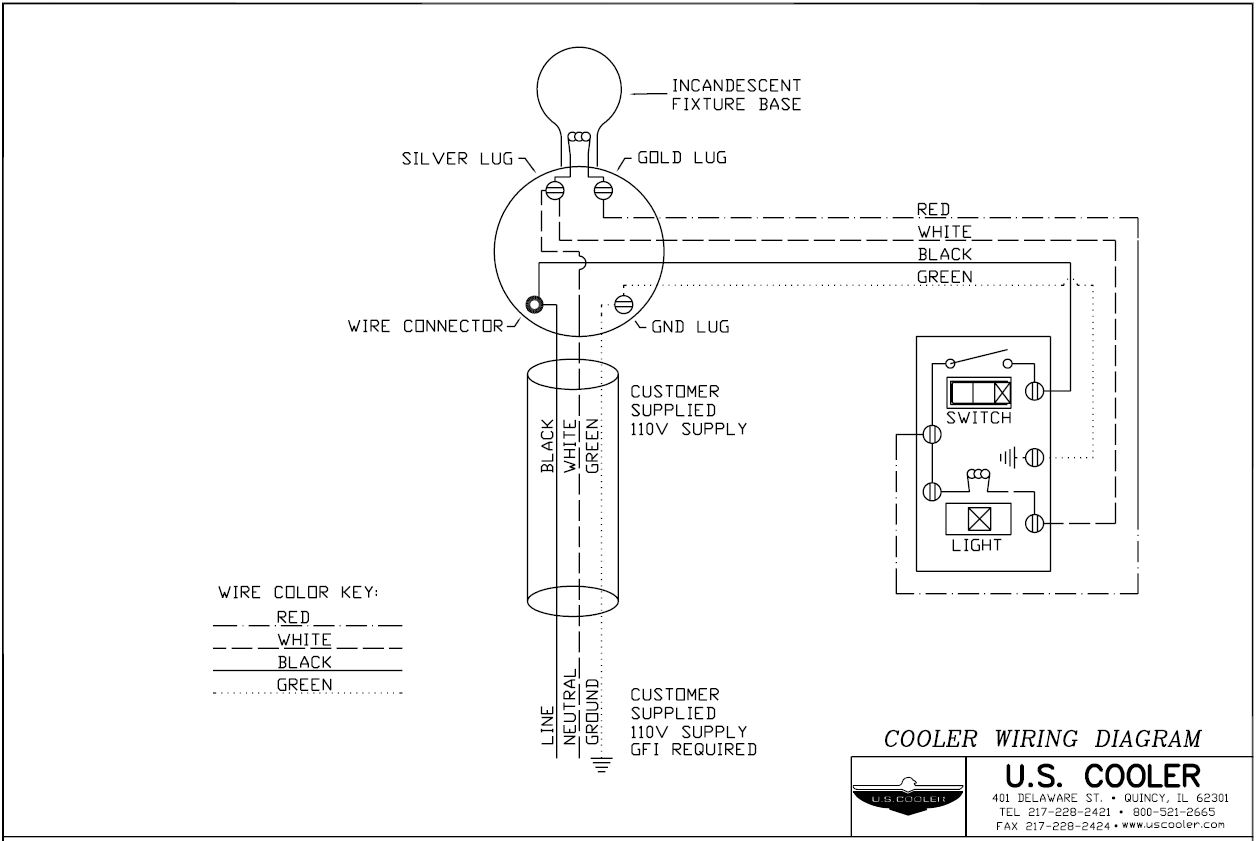
Typical Wiring Diagram For Two Door Cooler

Cooler Wiring Diagram U S Cooler 1. gather the required tools and materials. before starting the wiring process, make sure you have all the necessary tools and materials. these may include wire cutters, wire strippers, a screwdriver, electrical tape, wire nuts, conduit, and the appropriate electrical wiring for your specific walk in cooler model. Title: walk in cooler & freezer electrical drawings author: u.s. cooler created date: 7 17 2009 10:18:39 am.

Typical Wiring Diagram Walk In Cooler Wiring Diagram Here are some steps to wire a walk in cooler: 1. plan the electrical layout. before starting the wiring process, it is crucial to plan the electrical layout of the walk in cooler. this includes determining the location of the power source, the placement of outlets, switches, and any other electrical components. The wiring diagram is a detailed schematic that shows the connections between the different electrical components in the walk in cooler. it provides a visual representation of how the power supply, switches, controls, and other electrical devices are connected to each other. understanding the wiring diagram is crucial for electricians. Click the following to view u.s. cooler ® freezer design drawings:. u.s. cooler ® drawings. includes door, electrical, refrigeration, ceiling & footing drawings. The electrician will have to install: two 208 240v surface mount outlet boxes to plug in the a cs, inside the cooler – one outlet box per a c and installed on the right side each a c. on the right side of each a c.one 120v supply via conduit to the front light atop the door to provide power to the light and the factory pre .

Walk In Cooler Wiring Schematic Click the following to view u.s. cooler ® freezer design drawings:. u.s. cooler ® drawings. includes door, electrical, refrigeration, ceiling & footing drawings. The electrician will have to install: two 208 240v surface mount outlet boxes to plug in the a cs, inside the cooler – one outlet box per a c and installed on the right side each a c. on the right side of each a c.one 120v supply via conduit to the front light atop the door to provide power to the light and the factory pre . With the hooks pointing in the same direction as the pins on the cam locks in the floor, place the hooks of the threshold bar into the slots of the cams. push the bar in the direction of the pin of the cam lock until they contact. gently tap the locking bar until it locks into the cams or quits moving. this movement is about. 1 1⁄2”. 1.2. the abcs of electrical wiring. voltage, current, resistance – these aren’t just fancy words. they’re the building blocks of any electrical system. and understanding them is as crucial as knowing your brisket from your ribs. 2. decoding the walk in cooler wiring diagram. 2.1. thermostats: the brain of the operation.

Cooler Complete Wiring Cooler Connection With Regulator Switch Youtube With the hooks pointing in the same direction as the pins on the cam locks in the floor, place the hooks of the threshold bar into the slots of the cams. push the bar in the direction of the pin of the cam lock until they contact. gently tap the locking bar until it locks into the cams or quits moving. this movement is about. 1 1⁄2”. 1.2. the abcs of electrical wiring. voltage, current, resistance – these aren’t just fancy words. they’re the building blocks of any electrical system. and understanding them is as crucial as knowing your brisket from your ribs. 2. decoding the walk in cooler wiring diagram. 2.1. thermostats: the brain of the operation.

Comments are closed.