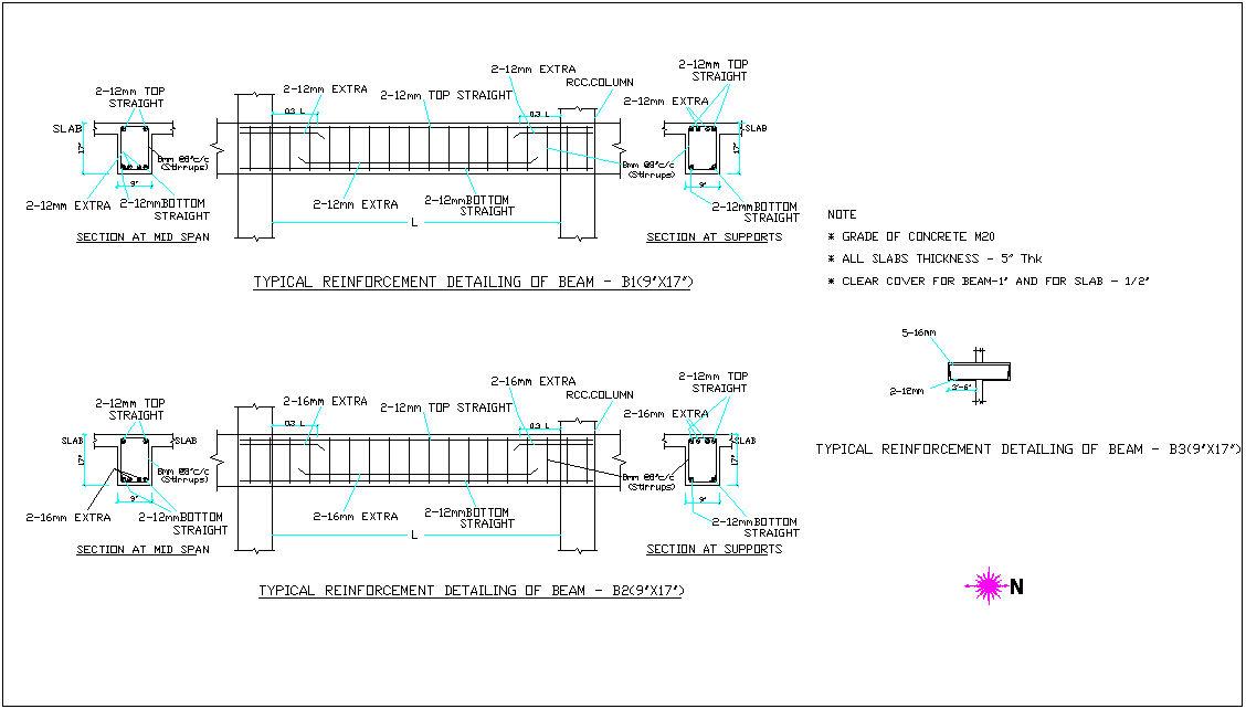
Typical Reinforcement Detail Of Beam With Structure View For Admin

Typical Reinforcement Detail Of Beam With Structure View For Admin Reinforcement details of concrete beams and slabs should specify clearly about cover to reinforcement, length of reinforcement, curtailment of reinforcement, number and diameter of reinforcement to be provided. for a simply supported beam and slab, the maximum bending moment occurs at the center of the span and shear force at a distance of d 2. 92)details and detailing199. the rights of. crete industry are stated more clearly by providing. specifications for . 315 highway bridges,” pg. (in.) for standard end hooks on grade 60 bars in. (in.) for standard end hooks on grade 60 bars in. 1.3 engineering drawings buildings and other struc .

Typical Beam Construction And Reinforcement Details Dwg File вђ Artofit Typical detailing of a reinforced concrete beam. the technical guides to the detailing and arrangement of beam reinforcements are as follows; (1) confirm the formwork dimensions and stability. beam reinforcement placement commences immediately after the carpenters complete the soffit formwork of the floor. Clearly, the detailing of the reinforced concrete members is the key to good design and execution of work at the site.that is why poor detailing of reinforcement makes the structure undergo cracking, excessive deflection, or even collapse. reinforcements resist tensile forces. they may also be required in the compression zones to increase the. The column footing and pier reinforcing bars are shown in schedules. in drawing wall elevations where footing steps occur, the detailer refers to the “typical stepped footing” detail on the structural drawing and footing elevations on the plan view. the exact horizontal location of these steps, however, is not given. Chapter 2—standa rds of practice, p. 315 3. 2.8—joint details 2.9—reinforcing steel supports 2.10—special details for seismic design of frames, joints, walls, diaphragms, and two way slabs 2.11—corrosion resistant coatings for reinforcing steel. aci 315 99 supersedes aci 315 92 and became effective august 31, 1999.

Comments are closed.