Solved Design The Slider Crank Mechanism With The Following Chegg

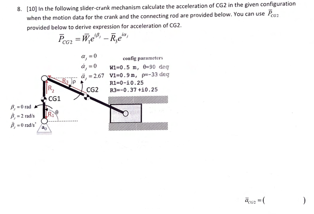
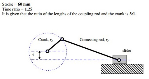
Solved 8 10 In The Following Slider Crank Mechanism Chegg Design a slider crank mechanism with the following performance criteria: stoke = 60 mm time ratio = 1.25 it is given that the ratio of the lengths of the coupling rod and the crank is 3:1. your solution’s ready to go!. The essential first step in developing kinematic equations for planar mechanisms via geometric relationships is drawing a picture of the mechanism in a general orientation, yielding equations that can be subsequently differentiated. figure 4.19. disassembled view of the slider crank mechanism for vector analysis.

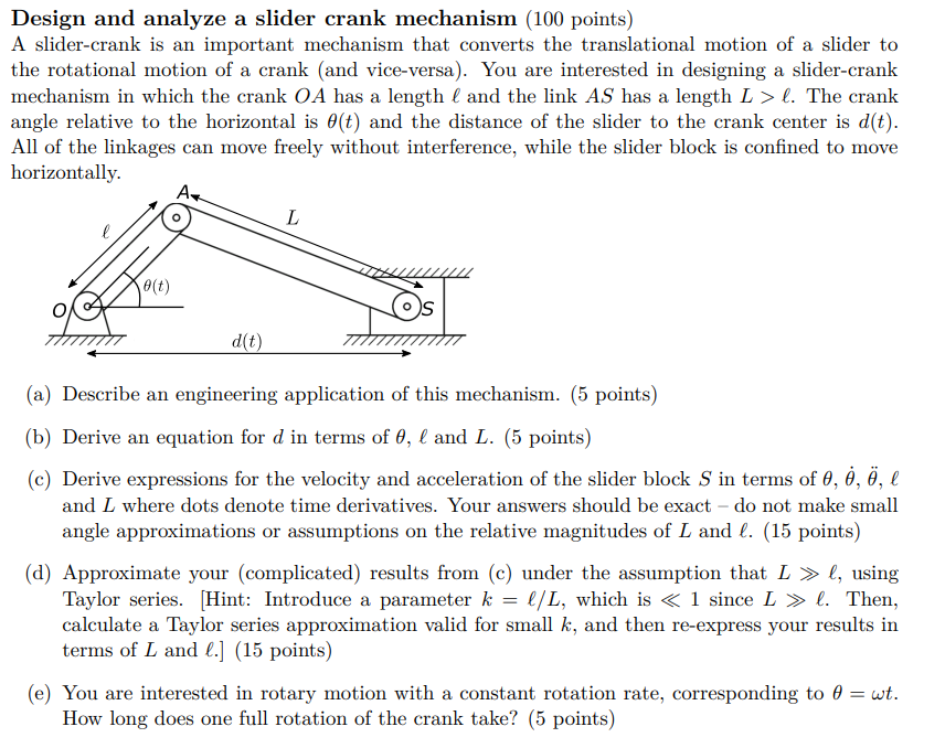
Solved Design And Analyze A Slider Crank Mechanism 100 Chegg Instant centers: slider crank mechanism. consider the mechanism shown below made up of moveable links ab, bd and slider d. link ab is rotating ccw at a constant rate. point c is the center of rotation for bd, where point c is at the intersection of perpendiculars to the velocities of points b and d. therefore, the velocity of any point on bd is. Abstract. the slider crank mechanism is a particular four bar linkage configuration that exhibits both linear and rotational motion simultaneously. this mechanism is frequently utilized in undergraduate engineering courses to investigate machine kinematics and resulting dynamic forces. the position, velocity, acceleration and shaking forces. Ii. development of dynamic equation of a in line crank slider mechanism. figure 3 represent the schematic of a crank slider mechanism. figures 4 6 represent the free body diagrams and kinetic diagrams for the crank (assumed to be a circular disc), connecting rod and the slider (piston) of a general crank slider mechanism, where the input. 2.1.dynamic analysis of a slider crank mechanism to obtain an initial understanding of the dynamic behaviour of a slider crank mechanism loaded with a spring, the equations of motion can be estab lished using fig. 1a. the following kinetic energy (t) and potential energy (v) formulations can be derived. assuming a uniform material distribution.

Solved Design A Slider Crank Mechanism With The Following Che Ii. development of dynamic equation of a in line crank slider mechanism. figure 3 represent the schematic of a crank slider mechanism. figures 4 6 represent the free body diagrams and kinetic diagrams for the crank (assumed to be a circular disc), connecting rod and the slider (piston) of a general crank slider mechanism, where the input. 2.1.dynamic analysis of a slider crank mechanism to obtain an initial understanding of the dynamic behaviour of a slider crank mechanism loaded with a spring, the equations of motion can be estab lished using fig. 1a. the following kinetic energy (t) and potential energy (v) formulations can be derived. assuming a uniform material distribution. Four bar linkage analysis: slider crank july 14, 2009 0 comments by prof. mccarthy the slider crank is an important mechanism with a wide range of applications. Slider crank mechanism, arrangement of mechanical parts designed to convert straight line motion to rotary motion, as in a reciprocating piston engine, or to convert rotary motion to straight line motion, as in a reciprocating piston pump. the basic nature of the mechanism and the relative motion of the parts can best be described with the aid.

Comments are closed.