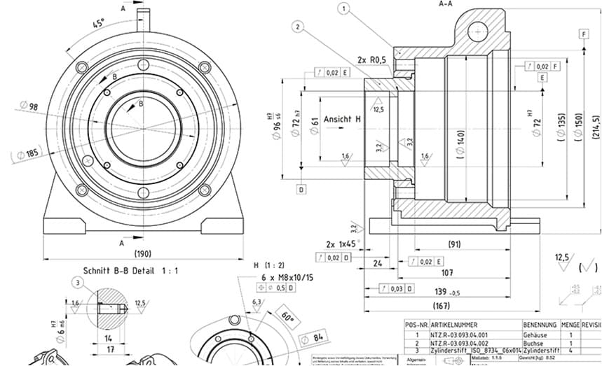
Reference Drawings Blueprints

New Or Required Point Elevation Building Section Reference Drawing Units of measurement. the units of the print are very important because there is a huge difference between 25.4mm and 25.4 inches. the measurement units will often be called out in the title block or tolerance block but occasionally will be in another section of the blueprint such as in the notes. angular units are important also but there is. Labelling a drawing and having the text on the drawing can clutter the information. make sure you keep the labels aligned and slightly away from the drawing to keep things clear. if you are using arrows, try to keep them all at the same angles. a good option is vertical, horizontal and 45 degree angle only if possible.

Ak 47 Blueprint Download Free Blueprint For 3d Modeling A reference dimension is just what it sounds like. it is a dimension shown for reference. in other words it is there for informational purposes only. they are not a requirement in any way. reference dimensions can be used to clarify other dimensions on a drawing. in some instances, they make a drawing easier to understand. Blueprints can be larger or smaller depending on the scope and complexity of a project. the most common sizes of blueprints for the construction of a new home are 18×24 inches or 24×36 inches. in addition to the central drawing, each sheet of a blueprint usually includes the following features. 1. title block. the title block usually contains:. Determine the view. with 2d blueprints, there are three common perspectives: plan, elevation, and section. understanding which one of these is being employed is an important first step to reading any drawing. plan: a bird's eye view of planned work. usually this is done on a horizontal plane at 30" above the floor. Here are the six most common types of symbols you will find on floor plans (versus other types of plans). 1. compass. the north arrow tells you about the orientation of the property. builders and architects use “project north” as a designation, which is different from the cardinal directions on a compass.

Blueprint Maker How To Make Blueprints In Autocad Determine the view. with 2d blueprints, there are three common perspectives: plan, elevation, and section. understanding which one of these is being employed is an important first step to reading any drawing. plan: a bird's eye view of planned work. usually this is done on a horizontal plane at 30" above the floor. Here are the six most common types of symbols you will find on floor plans (versus other types of plans). 1. compass. the north arrow tells you about the orientation of the property. builders and architects use “project north” as a designation, which is different from the cardinal directions on a compass. Construction drawing symbols ensure that construction documents are clear, concise and universally interpretable, facilitating global collaboration and contributing to the efficiency and success of construction projects. the standardization of these symbols by the iso upholds uniformity and clarity within the industry, ensuring that the symbols. 3. use the dimension scale where measurements are not provided. as a rule, architectural plans are drawn to a "scale". an example would be, 1 inch (2.5 cm) equals 10 feet (3 m) (1"=10'), so measuring between to walls on the plan sheet means for each inch, the distance is 10 feet (3.0 m).

Character Sheet Drawing Reference Blueprints Construction drawing symbols ensure that construction documents are clear, concise and universally interpretable, facilitating global collaboration and contributing to the efficiency and success of construction projects. the standardization of these symbols by the iso upholds uniformity and clarity within the industry, ensuring that the symbols. 3. use the dimension scale where measurements are not provided. as a rule, architectural plans are drawn to a "scale". an example would be, 1 inch (2.5 cm) equals 10 feet (3 m) (1"=10'), so measuring between to walls on the plan sheet means for each inch, the distance is 10 feet (3.0 m).

Lambretta Jet 200 1975 Free Blueprint Cgfrog Com Blueprint Drawing

Comments are closed.