Reference Dimension On A Drawing

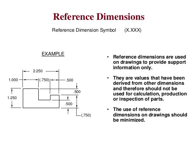
Reference Dimension Engineering Drawing вђ Nbkomputer A reference dimension is just what it sounds like. it is a dimension shown for reference. in other words it is there for informational purposes only. they are not a requirement in any way. reference dimensions can be used to clarify other dimensions on a drawing. in some instances, they make a drawing easier to understand. Reference dimension. a reference dimension is a dimension on an engineering drawing provided for information only. [1] reference dimensions are provided for a variety of reasons and are often an accumulation of other dimensions that are defined elsewhere [2] (e.g. on the drawing or other related documentation).

Reference Dimensions On Drawings Drawing Rjuuc Edu Np "the method for identifying a reference dimension (or reference data) on drawings is to enclose the dimension (or data) within parentheses. see figs. 1 19 and 1 20." re: asme y14.5 standard for reference dimensions?. Basic dimensions are typically used within the gd&t framework to control the location or geometry of features. the best example of when basic dimensions are used is when specifying true position. take a look at this drawing below: the basic dimensions are those dimensions in the boxes – the 30 and the 15. they do have tolerances, though, as. Explanations for reference dimensions, basic dimensions, and inspection dimensions in gd&t are provided in this video. This is called unidirectional dimensioning. the aligned method (where text is placed parallel to the dimension line) may be seen on older drawings or on architectural drawings but is not approved by the current ansi standard. group dimensions in standard practice, dimensions are grouped on a drawing for uniform appearance.

Comments are closed.