Process Flow Diagram For Cooling Tower

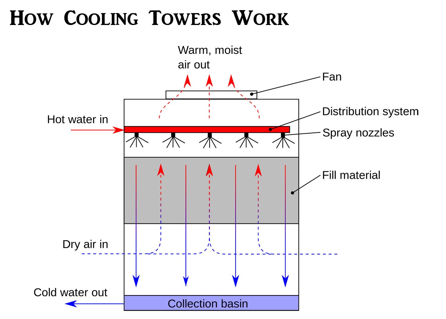
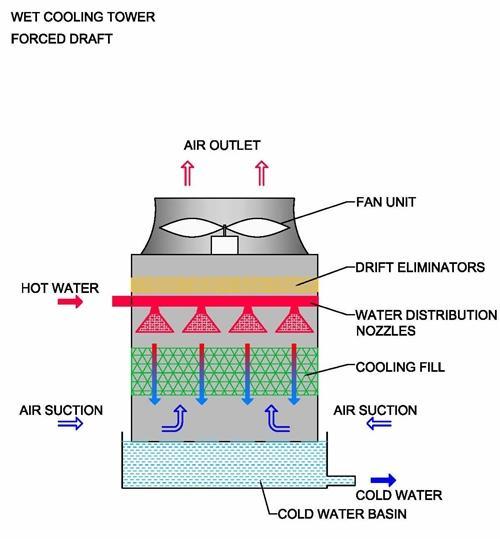
How Cooling Towers Work W Diagram Pictures Principles 2018 A cooling tower flow diagram is a visual representation of the process of removing heat from a system through the use of a cooling tower. this diagram provides a clear overview of how water is circulated and cooled in the tower, allowing for efficient cooling of industrial processes and equipment. The components of a cooling tower. a cooling tower is made up of several key components that work together to facilitate the cooling process. these components include: 1. fan. the fan is responsible for creating airflow within the cooling tower, which helps to draw in ambient air and expel hot air.

Mechanical Engineering An Overview Of A Cooling Tower Indicating Flow Cooling tower spouts are managed to diffuse the water over the “fill media,” that reduces the flow of water and reveals the maximum volume of water covering area desirable for the safest air water connection. the water is flashed to air as it passes throughout the cooling tower. the air has been pulled using a motor driven electrical. Cooling tower air flowing past fill packaging. combining the spray of water, the thin film of water on the fill packaging and the flow of cool air you get a great amount of heat transfer. flow of air and condenser water. just to recap. warm condenser water enters the tower and is sprayed over the fill packaging. The water is exposed to air as it flows throughout the cooling tower. the air is being pulled by an motor driven electric “cooling tower fan”. when the air and water come together, a small volume of water evaporates, creating an action of cooling. the colder water gets pumped back to the process equipment that absorbs heat or the condenser. Sequence of operation. when the operating fan(s) are operating at 50 percent speed, an additional fan shall be enabled and controlled at the same speed as the operating fans until all active cooling tower cell fans are enabled. when operating fans are running at minimum speed and the tower supply water temperature is five (5) degrees below the.
2 Process Flow Diagram Of A Cooling Tower Download Scientific Diagr The water is exposed to air as it flows throughout the cooling tower. the air is being pulled by an motor driven electric “cooling tower fan”. when the air and water come together, a small volume of water evaporates, creating an action of cooling. the colder water gets pumped back to the process equipment that absorbs heat or the condenser. Sequence of operation. when the operating fan(s) are operating at 50 percent speed, an additional fan shall be enabled and controlled at the same speed as the operating fans until all active cooling tower cell fans are enabled. when operating fans are running at minimum speed and the tower supply water temperature is five (5) degrees below the. Crossflow cooling towers flow diagram in crossflow cooling tower systems the water vertically flows through the fill media while the air horizontally flows across the falling water. that's why they call it "crossflow" because the air and water cross paths or flows. because of the crossing of flows, the air doesn't need to. The cooling tower process flow diagram is a useful tool for understanding the overall operation of a cooling tower system. it provides a visual representation of the steps involved in heat transfer and highlights the key components involved in the process.

Cooling Tower Diagram A Go To Guide To Learn About Their Function Crossflow cooling towers flow diagram in crossflow cooling tower systems the water vertically flows through the fill media while the air horizontally flows across the falling water. that's why they call it "crossflow" because the air and water cross paths or flows. because of the crossing of flows, the air doesn't need to. The cooling tower process flow diagram is a useful tool for understanding the overall operation of a cooling tower system. it provides a visual representation of the steps involved in heat transfer and highlights the key components involved in the process.

Comments are closed.