Piston And Rod Forces In A Crankshaft Mechanism Fully Assembled By Contacts

Piston And Rod Forces In A Crankshaft Mechanism Fully Assembl About press copyright contact us creators advertise developers terms privacy policy & safety how works test new features nfl sunday ticket press copyright. Assuming a peak combustion pressure of 120 bar (1740 psi), that peak combustion pressure will produce a downward force on the piston crown of 21,866 pounds, calculated as follows: piston area x applied pressure = applied force. 4.000 ² x 0.7854 x 1740 psi = 21,866 pounds. calculation 1: peak piston force from combustion.

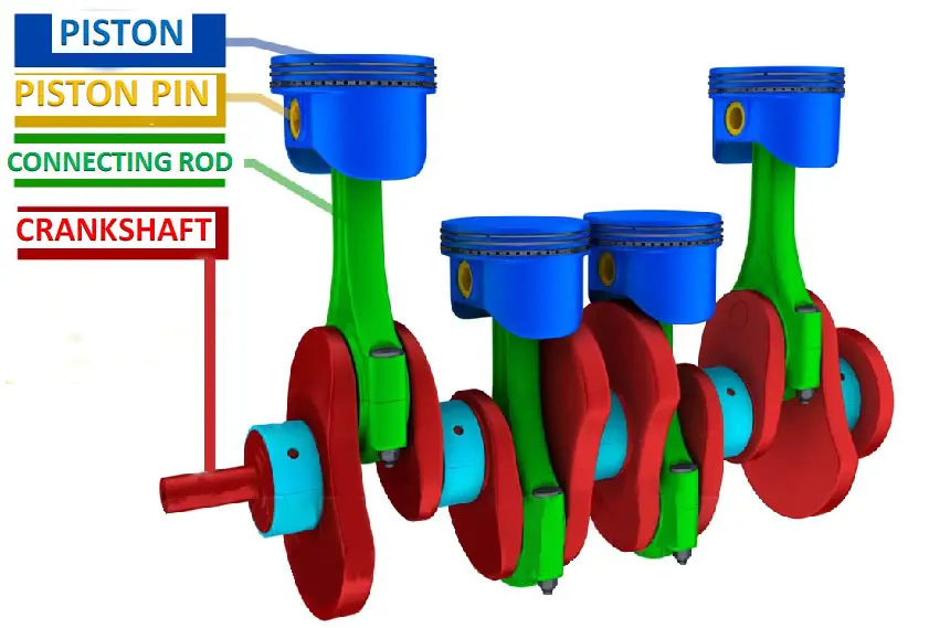
A Crankshaft Connecting Rod Piston System B Forces On Piston And 1.1 function and requirements of crankshaft assemblies. together with both the piston pins and the crankshaft’s crank pins, the connecting rod in reciprocating piston engines converts oscillating piston motion into rotary crankshaft motion. running smoothness is a universally important criterion for the design of crankshaft assemblies. In reciprocating pumps or compressors, the purpose of the crankshaft is to convert rotary motion from an electric motor or other prime mover into the reciprocating motion used to reciprocate the piston. the crankshafts start rotating with the starting of the motor. this causes the connecting rod to oscillate, resulting in the to and fro motion. Piston slider crank mechanism design equations. displacement of piston slider: angular velocity of connecting rod: linear velocity of piston slider: angular accerelation on connecting rod: piston slider acceleration: where: l = length of connecting rod (in, mm), r = radius of crank (in, mm), x = distance from center of crankshaft a to wrist. Slider – crank mechanism for demonstration and experimentation page 6 background the assembly of a piston, cylinder, connecting rod and crankshaft is the classic form of the slider crank mechanism. in general a slider crank transmits motion generated by the linear displacement of the piston by a working fluid to rotational motion of a shaft.

The External Forces And Moments Of Cylinder Piston Rod Crank System Piston slider crank mechanism design equations. displacement of piston slider: angular velocity of connecting rod: linear velocity of piston slider: angular accerelation on connecting rod: piston slider acceleration: where: l = length of connecting rod (in, mm), r = radius of crank (in, mm), x = distance from center of crankshaft a to wrist. Slider – crank mechanism for demonstration and experimentation page 6 background the assembly of a piston, cylinder, connecting rod and crankshaft is the classic form of the slider crank mechanism. in general a slider crank transmits motion generated by the linear displacement of the piston by a working fluid to rotational motion of a shaft. Kinematics of crank mechanism. crank mechanism comprises of piston, connecting rod and crank shaft. in formulation of the crank mechanism such as piston kinematics and connecting rod kinematics of an engine need parameters of already existing engine, the given parameters are stated in table 1 and 2. table 1. The paper deals with study of an assembly of the piston, connecting rod and crank shaft of a four wheeler petrol engine. the components of the assembly have to be rigid and the assembly has to move as a mechanism. hence, the analysis should involve a rigid body analysis and flexible body analysis. so the forces in the components as the engine.

Anatomy Of A Crankshaft Kinematics of crank mechanism. crank mechanism comprises of piston, connecting rod and crank shaft. in formulation of the crank mechanism such as piston kinematics and connecting rod kinematics of an engine need parameters of already existing engine, the given parameters are stated in table 1 and 2. table 1. The paper deals with study of an assembly of the piston, connecting rod and crank shaft of a four wheeler petrol engine. the components of the assembly have to be rigid and the assembly has to move as a mechanism. hence, the analysis should involve a rigid body analysis and flexible body analysis. so the forces in the components as the engine.

Diagram Of The Connecting Rod Piston Group Showing The Forces And

Comments are closed.