Phase Diagram Cooling Curve Eutectic

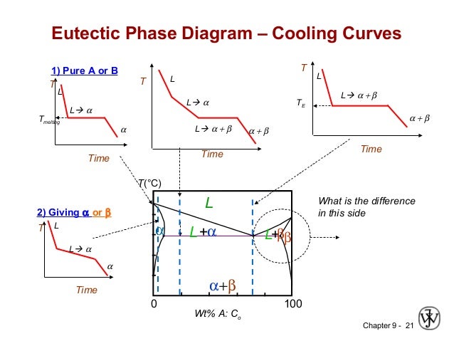
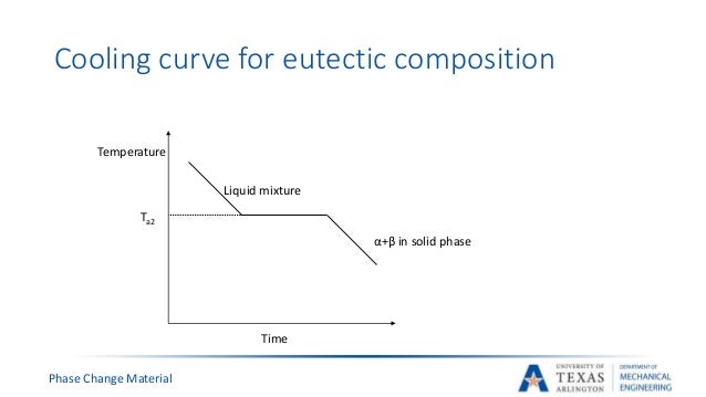
Phase Diagram Cooling Curve Eutectic вђ Rainy Weathers By removing the time axis from the curves and replacing it with composition, the cooling curves indicate the temperatures of the solidus and liquidus for a given composition. this allows the solidus and liquidus to be plotted to produce the phase diagram: this page titled 12.5: interpretation of cooling curves is shared under a cc by nc sa. This results in a cooling curve similar in shape to that of a single component system with the system solidifying at its eutectic temperature. when solidifying hypoeutectic or hypereutectic alloys, the first solid to form is a single phase which has a composition different to that of the liquid.

Ch09 M Liquid solid phase diagrams: tin and lead. The construction of an eutectic phase diagram from cooling curves is depicted for the copper silver alloy system in figure 4. the pure metal compositions, a and f, and the eutectic, d, have cooling curves with a "thermal arrest" only, i.e. no other break in the curve. A cooling curve for a sample that begins at the temperature and composition given by point a is shown in figure 8.10.1b 8.10. 1 b. figure 8.10.1 8.10. 1: (a) cooling of a two component system from liquid to solid. (b) cooresponding cooling curve for this process. as the sample cools from point a, the temperature will decrease at a rate. The cooling curve for liquid of this composition would display a halt at the melting point. the phase diagram in fig. 13.3 has two eutectic points. it resembles two simple phase diagrams like fig. 13.1 placed side by side.

Binary Eutectic System Construction Of Phase Diagram Cooling Curve A cooling curve for a sample that begins at the temperature and composition given by point a is shown in figure 8.10.1b 8.10. 1 b. figure 8.10.1 8.10. 1: (a) cooling of a two component system from liquid to solid. (b) cooresponding cooling curve for this process. as the sample cools from point a, the temperature will decrease at a rate. The cooling curve for liquid of this composition would display a halt at the melting point. the phase diagram in fig. 13.3 has two eutectic points. it resembles two simple phase diagrams like fig. 13.1 placed side by side. Lecture 19: 11.23.05 binary phase diagrams. The phase diagram. constructing the phase diagram. you start from data obtained from the cooling curves. you draw a graph of the temperature at which freezing first starts against the proportion of tin and lead in the mixture. the only unusual thing is that you draw the temperature scale at each end of the diagram instead of only at the left.

Submitted Presentation Lecture 19: 11.23.05 binary phase diagrams. The phase diagram. constructing the phase diagram. you start from data obtained from the cooling curves. you draw a graph of the temperature at which freezing first starts against the proportion of tin and lead in the mixture. the only unusual thing is that you draw the temperature scale at each end of the diagram instead of only at the left.

Intoduction Phase Diagrams Physical Metallurgy

Comments are closed.