Gm Astro Power Steering Hose Diagram Q A For Hydroboost Steering Li

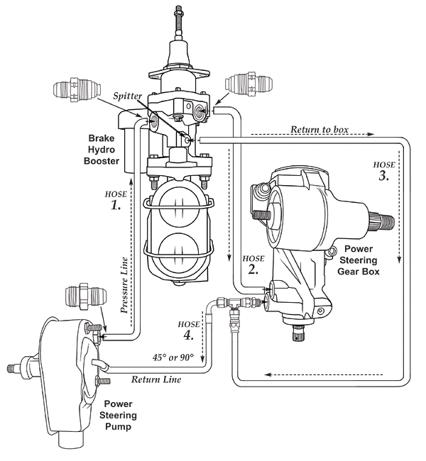
Gm Astro Power Steering Hose Diagram Q A For Hydroboost It is easier to understand with a diagram. the high pressure power steering pump output goes to the high pressure input on the hydroboost. the high pressure output on the hydroboost goes to the high pressure input on the steering box. the low pressure line on the steering box and the third, low pressure line on the hydroboost go to the tee. This is why the chart listed the "minimum" working pressures. you "must" have 1425 to 1525 psi relief when the steering is turned to "the locked" position. 8 to 1300 psi is nice for a car, but your truck requires at least 1425 psi before the pressure relief valve releases.

Gm Astro Power Steering Hose Diagram Q A For Hydroboost Check around the hydroboost and look for another leak, such as the accumulator, the upper lines and fittings. could be that something else is leaking on you. could be the master cylinder rear seal. smell the brake fluid and then smell the power steering fluid. My astro power steering pump was making horrible noises, so i replaced it and all of the lines. Yes, it is tight and not easy. power steering pump replacement. removal procedure. remove the power steering pump pulley. place a drain pan under the vehicle. important: cap or plug the ends of the power steering hoses to prevent fluid loss. disconnect the power brake booster inlet hose from the power brake booster. Dont forget that ground wire on the side bolt or the bracket on the front. press the pulley back on and reinstall the serp belt. step 8: attach the hose that goes from the gearbox to the booster. this is hose number 7 in the parts picture, and the end with the 7 on it goes to the gear box.

Hydroboost 7 3 Power Steering Hose Diagram Yes, it is tight and not easy. power steering pump replacement. removal procedure. remove the power steering pump pulley. place a drain pan under the vehicle. important: cap or plug the ends of the power steering hoses to prevent fluid loss. disconnect the power brake booster inlet hose from the power brake booster. Dont forget that ground wire on the side bolt or the bracket on the front. press the pulley back on and reinstall the serp belt. step 8: attach the hose that goes from the gearbox to the booster. this is hose number 7 in the parts picture, and the end with the 7 on it goes to the gear box. Power steering & hydroboost schematics: [updated] i'm trying to sum up all the discussions on power steering and hydroboost schematics and line fittings onto one page. this is for a 2004 mach 1 donor without cooler. i created the image 8.5" x 11" at 300 dpi so it could be printed out clearly. This technique can be used on most power steering systems. bleed technique 2: 1. remove return line from hydro boost and plug end with appropriate size plug or bolt. 2. connect two to three foot piece of clear hose to return port on hydro boost unit. place end of hose into empty container at least 1 gallon in capacity. 3.

Comments are closed.