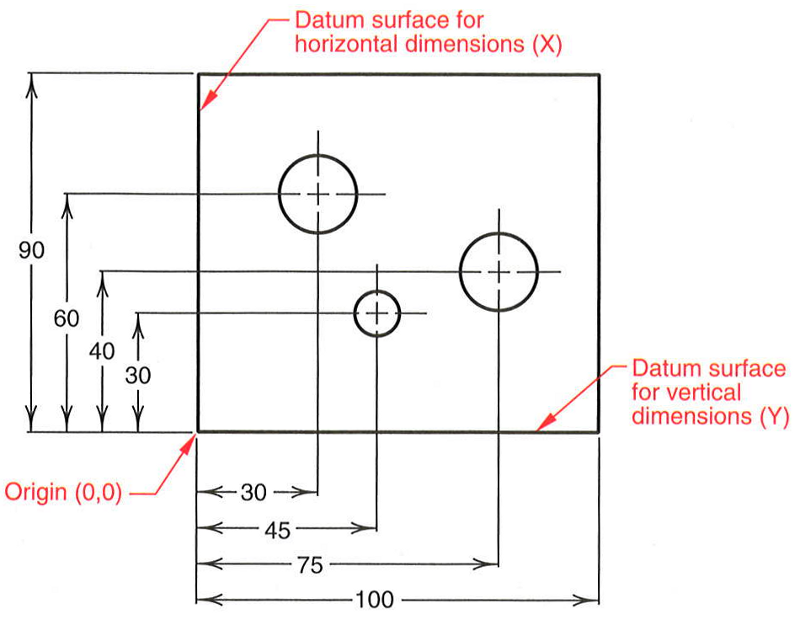
Fixed Common Reference Point Dimensioning Drawings

Fixed Reference Point With Disallowed Directions And Rotations For Using a fixed common reference point ensures consistency and accuracy in dimensioning, making it easier for multiple people to interpret the dimensions on a drawing or sketch. Principles of dimensioning | engineering design.

Reference Dimensions On Drawings Drawing Rjuuc Edu Np Dimensioning and tolerancing. 9.8. a size dimension might be the overall width of the part or the diameter of a drilled hole. a location dimension might be length from the edge of the object to the center of the drilled hole. 9.9 10. the location and orientation of dimensions are based on the three positions: horizontal, vertical, and angles. Essentially, dimensioning refers to the process of specifying the exact size, shape, and location of different parts and features on an engineering drawing. dimensioning is vital in the engineering industry as it ensures that the final product meets the required standards and specifications. it helps to minimize errors and inaccuracies during. A reference dimension is just what it sounds like. it is a dimension shown for reference. in other words it is there for informational purposes only. they are not a requirement in any way. reference dimensions can be used to clarify other dimensions on a drawing. in some instances, they make a drawing easier to understand.

Technical Drawing Dimensions Design Talk Essentially, dimensioning refers to the process of specifying the exact size, shape, and location of different parts and features on an engineering drawing. dimensioning is vital in the engineering industry as it ensures that the final product meets the required standards and specifications. it helps to minimize errors and inaccuracies during. A reference dimension is just what it sounds like. it is a dimension shown for reference. in other words it is there for informational purposes only. they are not a requirement in any way. reference dimensions can be used to clarify other dimensions on a drawing. in some instances, they make a drawing easier to understand. Dimensioning. dimensioning a technical drawing refers to the process of adding measurements and numerical values to indicate the size, location, and specifications of various elements in the drawing. these measurements provide important information for understanding the object's size, proportions, and how its components relate to each other. A datum reference can be along the straight edge of a design, known as datum surface, or a single datum point, often found in the corner of a design. in a circular shape, it would be around the.

Eng 004 Lecture 13 Dimensioning. dimensioning a technical drawing refers to the process of adding measurements and numerical values to indicate the size, location, and specifications of various elements in the drawing. these measurements provide important information for understanding the object's size, proportions, and how its components relate to each other. A datum reference can be along the straight edge of a design, known as datum surface, or a single datum point, often found in the corner of a design. in a circular shape, it would be around the.

Comments are closed.