Faq 004793 Is It Possible To Display The Results Of Shear Forces On A Member In The Horizontal

Faq 004793 Is It Possible To Display The Results Of Shear For Question:is it possible to display the results of shear forces on a member in the horizontal plane?answer:the view can be switched in the navigator in the ta. Hi @artur.kosakowski, yes, it is that simple! 🙂 it is just the shear force at the end of the member i need so i can complete a hand calculation to check the bolted connection. when i look at the forces table (taking member 283, at node 272 as an example from above), the max values i am getting for fz are not what i expect for the shear force.
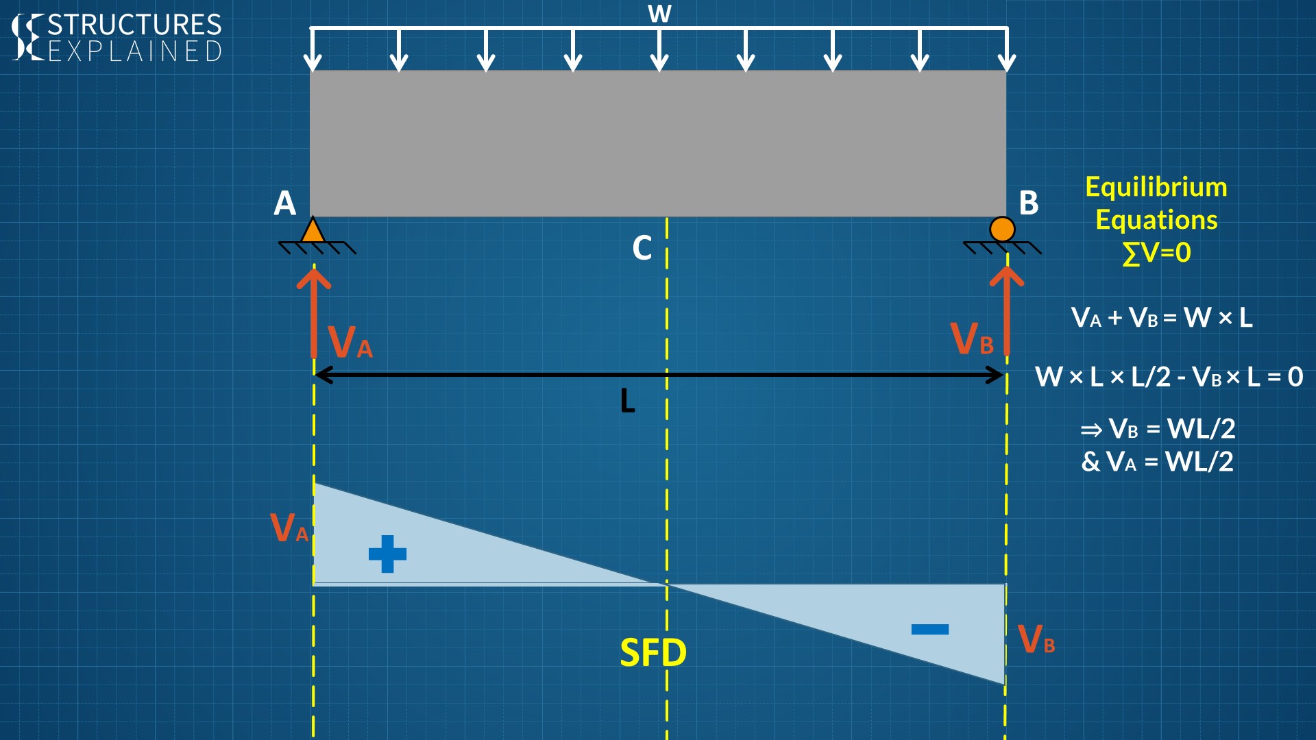
Shear Force And Bending Moment Diagram In The Horizontal Plane If you apply the fx (horizontal force) to the top corner of the wall the nyy map will show you the "horizontal" force distribution in this wall and fx reaction will correspond to the applied force. if you find your post answered press the accept as solution button please. this will help other users to find solutions much faster. thank you. Step 1 | draw a free body diagram. to correctly determine the shear forces and bending moments along a beam we need to know all of the loads acting on it, which includes external loads and reaction loads at supports. by drawing the free body diagram you identify all of these loads and show then on a sketch. Here are the steps, we are going to follow to calculate the shear forces: calculate the reaction forces a h, a v and b v. cut the beam at a location x. calculate the shear force at location x. repeat 2. and 3. to calculate the shear forces at different locations. 1. calculation of the reaction forces. 5 points : display the member forces calculated at both end nodes and the quarter points of each beam element. the diagram is presented by connecting the 5 points. no fill : display only the outline representing the magnitudes of the member forces. line fill : display the diagram filled in with color lines.

Horizontal Shear Force In A Beam The Best Picture Of Beam Here are the steps, we are going to follow to calculate the shear forces: calculate the reaction forces a h, a v and b v. cut the beam at a location x. calculate the shear force at location x. repeat 2. and 3. to calculate the shear forces at different locations. 1. calculation of the reaction forces. 5 points : display the member forces calculated at both end nodes and the quarter points of each beam element. the diagram is presented by connecting the 5 points. no fill : display only the outline representing the magnitudes of the member forces. line fill : display the diagram filled in with color lines. In case of a hinged connection, the bending moment in the connection is zero. diagrams of the bending moment and shear force in the hinge connected horizontal member are presented in the following figure. shear force v z = 40 kn and zero bending moment m y must be specified to induce corresponding internal forces in connection application. in. Shear diagram. to create the shear force diagram, we will use the following process. solve for all external forces acting on the body. draw out a free body diagram of the body horizontally. leave all distributed forces as distributed forces and do not replace them with the equivalent point load. lined up below the free body diagram, draw a set.

Ppt Shearing Stresses In Beams And Thin Walled Members Powerpoint In case of a hinged connection, the bending moment in the connection is zero. diagrams of the bending moment and shear force in the hinge connected horizontal member are presented in the following figure. shear force v z = 40 kn and zero bending moment m y must be specified to induce corresponding internal forces in connection application. in. Shear diagram. to create the shear force diagram, we will use the following process. solve for all external forces acting on the body. draw out a free body diagram of the body horizontally. leave all distributed forces as distributed forces and do not replace them with the equivalent point load. lined up below the free body diagram, draw a set.

Understanding Shear Force Diagram

Comments are closed.