Engineering Drawing Grid System

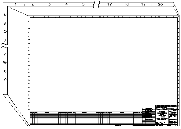
Engineering Drawing Grid System The typical ‘engineering’ style drawing border has a grid reference frame drawn into the border. the grid references are used for the location and coordination of details. grid line weights. the grid lines themselves are drawn with a 0.35mm line weight. they are spaced 50mm apart from the centring lines. the last two divisions can be. To help locate a specific point on a referenced print, most drawings, especially piping and instrument drawings (p&id) and electrical schematic drawings, have a grid system. the grid can consist of letters, numbers, or both that run horizontally and vertically around the drawing as illustrated below. like a city map, the drawing is divided into.

Technical Drawing Standards Grid Reference Frame Block, the notesand legend, and the drawing grid is necessarybefore a drawing can be read. this information is displayed in the areas surrounding the graphic portion of the drawing. eo 1.1 state the five types of information provided in the title block of an engineering drawing. eo 1.2 state how the grid system on an engineering drawing is used. In order for structural drawings to fit on a manageable sized drawing sheet, the drawing is usually a small fraction of the real world size. a scale of 1:100 is a very common scale to use for a structural framing plan. that is, a 1mm measurement taken on the drawing represents a 100mm length of the real world object. How to read structural elements notation using a grid on structural drawings. how to reference columns and beams on a floor plan.#structuraldrawings #gridref. The title block is one of the most essential elements of engineering drawings that contains all the relevant information needed to identify the drawing, e.g., part number, part name, drawing owner, designer name, etc. furthermore, a title block defines other relevant information, e.g., material, standard, perspective type, scale, page number.

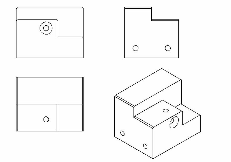
Engineering Drawing Views Basics Explained Fractory How to read structural elements notation using a grid on structural drawings. how to reference columns and beams on a floor plan.#structuraldrawings #gridref. The title block is one of the most essential elements of engineering drawings that contains all the relevant information needed to identify the drawing, e.g., part number, part name, drawing owner, designer name, etc. furthermore, a title block defines other relevant information, e.g., material, standard, perspective type, scale, page number. Block, the notes and legend, and the drawing grid is necessary before a drawing can be read. this information is displayed in the areas surrounding the graphic portion of the drawing. eo 1.1 state the five types of information provided in the title block of an engineering drawing. eo 1.2 state how the grid system on an engineering drawing is used. The gsfc engineering drawing standards manual is the official source for the requirements and interpretations to be used in the development and presentation of engineering drawings and related documentation for the gsfc. the mechanical engineering branch, mechanical systems division, has been delegated.

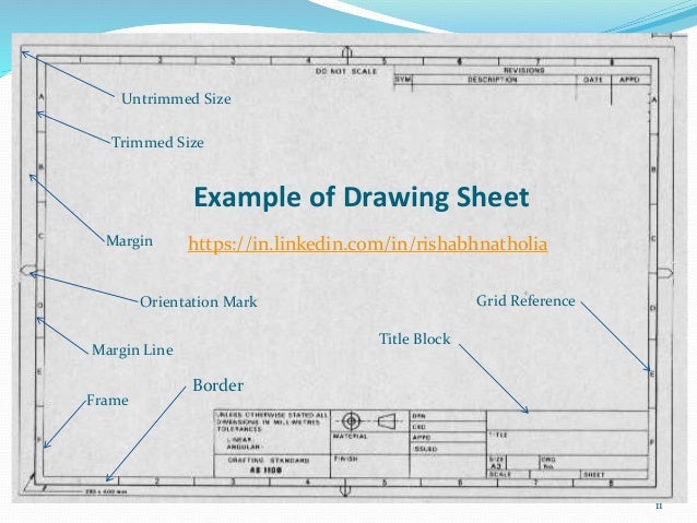
Basics Of Engineering Drawing By Rishabh Natholia Block, the notes and legend, and the drawing grid is necessary before a drawing can be read. this information is displayed in the areas surrounding the graphic portion of the drawing. eo 1.1 state the five types of information provided in the title block of an engineering drawing. eo 1.2 state how the grid system on an engineering drawing is used. The gsfc engineering drawing standards manual is the official source for the requirements and interpretations to be used in the development and presentation of engineering drawings and related documentation for the gsfc. the mechanical engineering branch, mechanical systems division, has been delegated.

Comments are closed.