Electric Motor Wiring Diagram Rectifier

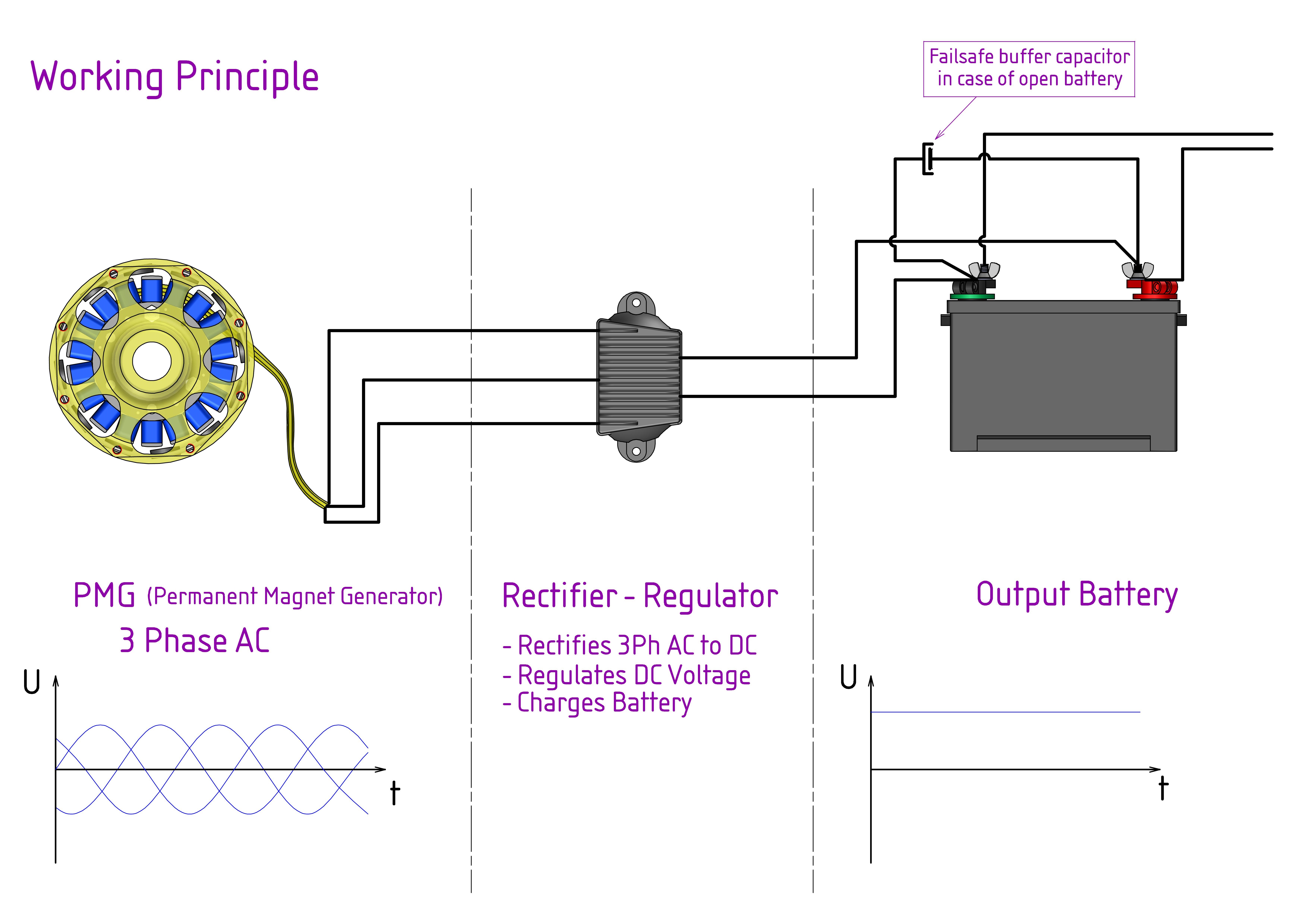
Electric Motor Wiring Diagram Rectifier The 3 phase regulator rectifier wiring diagram is an essential component in the electrical system of a three phase motorcycle or vehicle. it plays a crucial role in converting the ac voltage generated by the motorcycle’s alternator into dc voltage, which is necessary to charge the battery and power the motorcycle’s electrical system. a. This is where a 7 wire regulator rectifier comes into play. a 7 wire regulator rectifier has the ability to handle a higher output and provide a more stable voltage to your electrical system. it is typically used in vehicles with a higher wattage demand, such as off road bikes or custom motorcycles. this type of regulator rectifier has seven.

Electric Motor Wiring Diagram Rectifier Step 1: identify the motor’s wires. before beginning the wiring process, take a moment to identify the different wires coming from the motor. typically, you will find three main wires: the power wire, the neutral wire, and the ground wire. the power wire is usually black, the neutral wire is white, and the ground wire is usually green or bare. Brake control rectifier reactor. brake rectifiers or “brake control rectifiers” convert ac voltage to dc voltage. rectifiers are employed because most applications need ac energy to run the motor, but need dc power to control the brakes, which is rarely available. they can often be found in the terminal box, or “pecker head” usually. In the field of electrical engineering, a rectifier is a device that converts alternating current (ac) to direct current (dc). a rectifier wiring diagram is a visual representation of the circuitry and connections involved in a rectifier system. creating a wiring diagram for a rectifier can be a complex task, but by following a step by step. Motor brakes installation & maintenance. p. 2.60. 2.170.39pmg 500 push hybrid rectifierthe pmg 500 rectifier provides an initial “push” the form of a timed full wave brake release function, which is then fol lowed by a cont. nuous half wave brake holding function.in order to prevent rapid wear, the pmg 500 rectifier is required when.

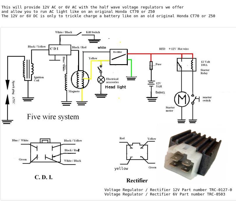
Electric Motor Wiring Diagram Rectifier In the field of electrical engineering, a rectifier is a device that converts alternating current (ac) to direct current (dc). a rectifier wiring diagram is a visual representation of the circuitry and connections involved in a rectifier system. creating a wiring diagram for a rectifier can be a complex task, but by following a step by step. Motor brakes installation & maintenance. p. 2.60. 2.170.39pmg 500 push hybrid rectifierthe pmg 500 rectifier provides an initial “push” the form of a timed full wave brake release function, which is then fol lowed by a cont. nuous half wave brake holding function.in order to prevent rapid wear, the pmg 500 rectifier is required when. 1) connect the motor to the mains as shown in the diagram inside the terminal block box (the wiring diagrams are also included at the end of this manual). 2) do not connect up or start the motor if the wiring diagram is absent. 3) do not start the motor with the key unengaged. Step 1: gather the necessary materials. before starting the wiring process, gather all the necessary materials. this includes a regulator rectifier, wiring harness, connectors, heat shrink tubing, electrical tape, and a wiring diagram for your specific motorcycle model.

Comments are closed.