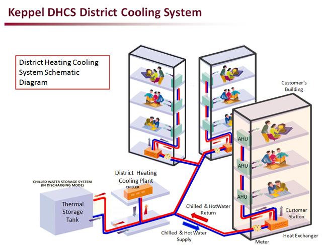
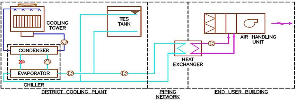
District Cooling System Schematic Diagram

District Cooling System Schematic Diagram The schematic diagram of a district cooling system shows the various components and processes involved in providing chilled water to the connected buildings. the system typically consists of a central plant, distribution network, and individual building connections. central plant: the central plant is where the chilled water is produced. Fig. a1 – elements of a district cooling system fig. b1 – air handling and terminal units fig. b2 – mixing valve at secondary side fig. c1 – gernal arrangment on construction of substation fig. c2 – ddc control schematic diagram in substation fig. c3 – typical layout of substation of two heat exchangers.

District Cooling System Schematic Diagram Marafeq's design guidelines for the connection of ets(s). Download scientific diagram | district cooling system in the des 229 from publication: a new distributed energy system configuration for cooling dominated districts and the performance assessment. District cooling system (dcs) becomes increasingly popular because of its high efficiency and high class cooling, especially in the areas with high density of buildings. dcs is defined as a system that distributes thermal energy in the form of chilled water from a central source to residential, commercial, institutional, and or industrial. The system's design schematic ( figure 1) and modelica diagram contain one to one modeling relationships, allowing users to clearly interpret the configuration. we connected the inlet and outlet.

What Are The Main Components Of A District Cooling System District cooling system (dcs) becomes increasingly popular because of its high efficiency and high class cooling, especially in the areas with high density of buildings. dcs is defined as a system that distributes thermal energy in the form of chilled water from a central source to residential, commercial, institutional, and or industrial. The system's design schematic ( figure 1) and modelica diagram contain one to one modeling relationships, allowing users to clearly interpret the configuration. we connected the inlet and outlet. Download scientific diagram | configuration of the large district cooling dc plant using block diagram [25]. from publication: life cycle assessment of an electric chiller integrated with a large. A district cooling (dc) system is a central air conditioning system that produces and distributes chilled water from a plant(s) to buildings, thus centralizing the production of chilled water and maximizing economy of scale. district cooling systems produce and deliver chilled water, or a secondary fluid, from a central source to consumers in a.

Comments are closed.