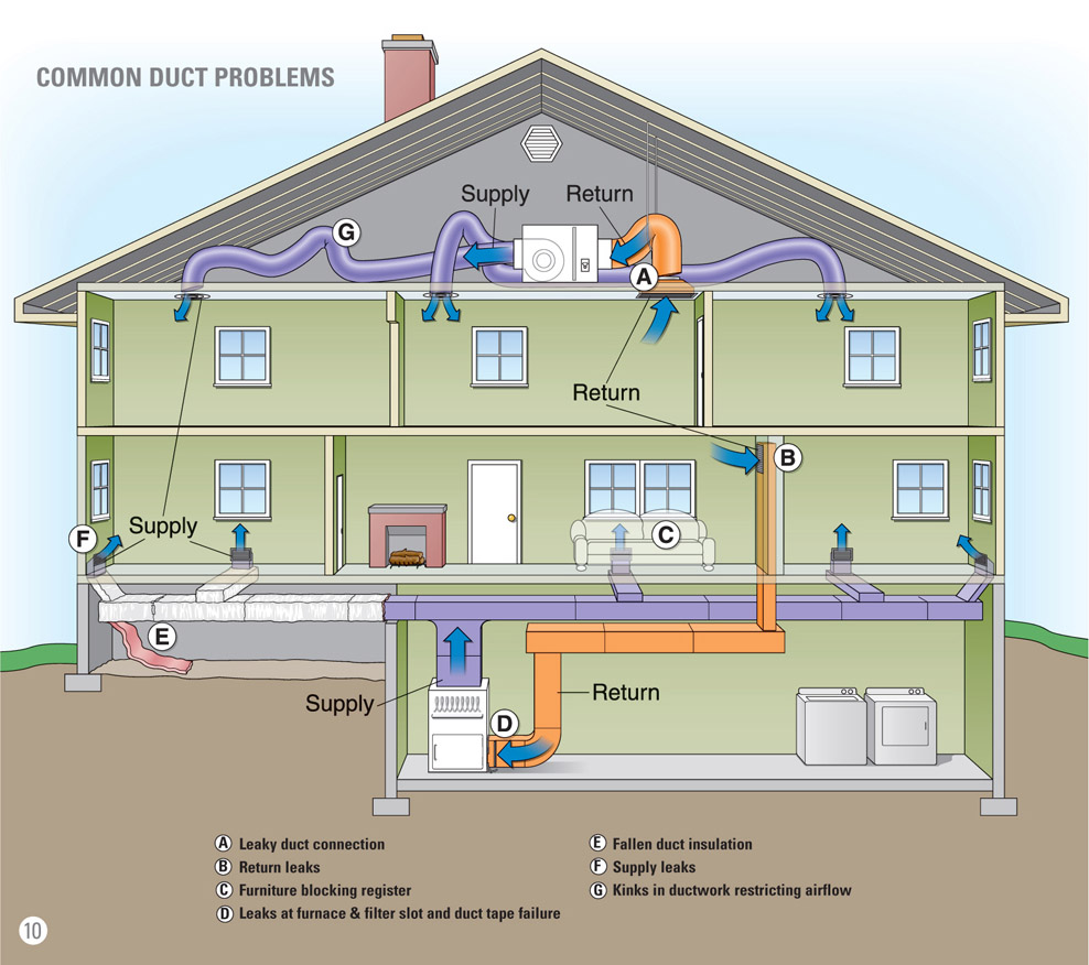
Diagram Of Central Heating Cooling Duct System

Hvac System Diagram Explained Example 2.5 ton duct system diagram. sizing for a 2.5 ton unit, we start with a 16" supply at 875 cfm 1125 cfm. we then take a 7" and 5" run ( 200 cfm) off of this. So, if you like to learn the basic design skills including this duct design, consider enrolling in the course. it’ll give you a head start. 1. calculate the cfm for each room. most hvac units are designed to have a 400 cfm of airflow for every 12000 btu or 1 ton of cooling capacity and 12000 btu divided by 400 cfm is 30.

Installing Central Air Conditioning A Comprehensive Guide This Old House Central cooling. if you have a split system, you will have a central cooling and a central heating unit. the central cooling unit works like this: first, warm air blows across the indoor evaporator coil. the heat energy then transfers to the refrigerant inside the coil. this transfer cools the air that passes across the coil. In a nutshell, a central hvac system heats or cools your home by feeding heated or cooled air through your ductwork. while the process seems simple, getting your home to the perfect temperature requires a lot of moving parts with a lot of different components at play. understanding the central heating and cooling processes will help you better. Check this out – there are 4 common air duct designs. the first is the plenum or radial duct system. radial systems have the hvac unit and return grill at the center of the home with the supply ducts extending out around the plenum like the legs of a spider. the second is the reducing extended plenum system. Ordinary heating, ventilating, and air conditioning duct systems read air pressures at 0.4 psi or less, often much less. 1 psi equals 27.7 inches of water gauge; a common duct pressure of 0.25 inches water column is equal to (0.25 divided by 27.7 in wc psi) = 0.009 psi. duct pressure: duct system is pressurized by three pressures: •.

Hvac Duct System Diagram Check this out – there are 4 common air duct designs. the first is the plenum or radial duct system. radial systems have the hvac unit and return grill at the center of the home with the supply ducts extending out around the plenum like the legs of a spider. the second is the reducing extended plenum system. Ordinary heating, ventilating, and air conditioning duct systems read air pressures at 0.4 psi or less, often much less. 1 psi equals 27.7 inches of water gauge; a common duct pressure of 0.25 inches water column is equal to (0.25 divided by 27.7 in wc psi) = 0.009 psi. duct pressure: duct system is pressurized by three pressures: •. Photo 5: supply runs. photo 6: boots (the top left two are different types of straight boots, while the bottom boot is an example of an ell boot and on the right, an end boot example) photo 7: return air panning. photo 8: pvc pipe and fittings used for the flu (chimney) on a high efficiency furnace. The air handler serves as the central hub in your hvac system. it houses the blower fan and filter, essential for moving air through the ductwork. the air handler may also include heating or cooling coils, further enhancing its role in air conditioning. drain pans and lines. hvac systems not only heat or cool the air but also dehumidify it.

This Simple Diagram Shows You How Your Hvac System S 49 Off Photo 5: supply runs. photo 6: boots (the top left two are different types of straight boots, while the bottom boot is an example of an ell boot and on the right, an end boot example) photo 7: return air panning. photo 8: pvc pipe and fittings used for the flu (chimney) on a high efficiency furnace. The air handler serves as the central hub in your hvac system. it houses the blower fan and filter, essential for moving air through the ductwork. the air handler may also include heating or cooling coils, further enhancing its role in air conditioning. drain pans and lines. hvac systems not only heat or cool the air but also dehumidify it.

Diagram Of Hvac Ducting System Residential

Comments are closed.