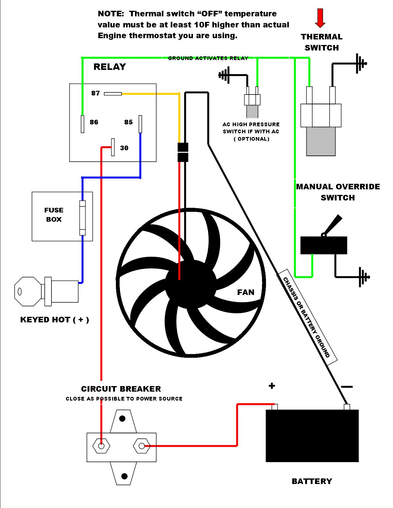
Derale Electric Fan Wiring Diagram More Wiring

Derale Fan Controller Wiring Diagram Closetal 2 relay wire harness 1 red butt connector 2 blue #10 ring terminals 2 blue 5 16” ring terminals 3 blue butt connectors 2 blue female connectors 4 blue wire tap connectors 7ft. 14 gauge wire 6 4” wire ties 4 #10 sheet metal screws derale performance, los angeles, ca 800.421.6288 derale diagram #1 engine puller fan air flow radiator. 9. using a yellow butt connector, connect the 10 awg black wire to the negative ( ) lead of the fan(s). route the other end of this wire to the fan ( ) terminal of the fan controller & connect using #8 yellow ring terminal. green wire: override circuit (optional) the green wire is designed to work in two different configurations. when used.

Derale Electric Fan Wiring Diagram Using a yellow butt connector and the supplied 10 ga. red wire, connect one end of the red wire to the #1 electric fan positive ( ) wire. run the 10 ga. red wire connected to the #1 electric fan positive lead to the red wire (closest to the adjustment screw). cut the wire to the appropriate length. connect wires using one of the supplied yellow. Using a table or workbench, lay the electric fan assembly on a flat surface, electric fan facing down. take the supplied rubber fan shroud seal and install it onto the bottom edge of the fan shroud assembly. (see diagram #4) cut off any excess rubber. identify the four angel brackets, 1 4 20 x 3 4” hex bolts, 1 4” flat washers & 1 4 20 lock. Shroud should be mounted tight against radiator to minimize air leaks that would reduce efficiency. mounting. 1. install the rubber fan shroud seal. (see diagram #4) 2. position the electric fan in the desired location. taking the. angle brackets supplied determine the best locations for a. Position the electric fan in the desired location. taking the angle brackets supplied, determine the best locations for a good rigid mount. (see diagram #2) take the four angle brackets, 1 4” hex bolts, washers and nyloc nuts provided and attach brackets to the fan shroud in the desired location. in some applications where the radiator flange.

Comments are closed.