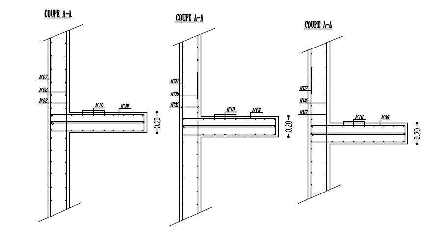
Cross Section Of Beam And Column With Reinforcement Details In Auto

Cross Section Of Beam And Column With Reinforcement Details In A In this video, you learn to draw complete detailing of the reinforced beam. this video cover l section detailing and cross section detailing of the reinfor. Here are the general steps involved in reinforcement detailing in beams: determine the loads and load combinations that the beam must support, and the span of the beam. determine the size and shape of the beam cross section, based on the loads and span requirements. common beam shapes include rectangular, circular, and i shaped.

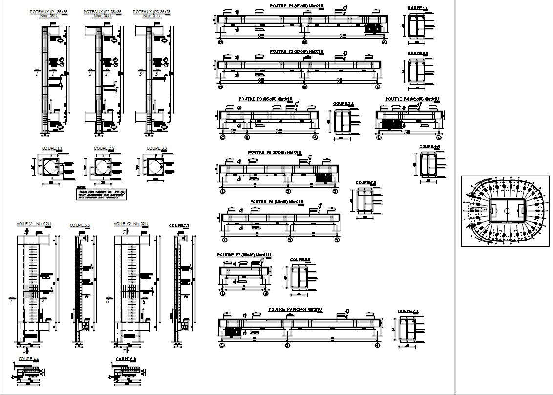
Cross Sections And Reinforcement Of The Columns And Beams Download T the reinforcement module of autocad. structural detailing: click asd ‐ start h (reinforcement). click asd . structure elements h structure elements ‐ formwork h (. m). alternatively, click reinforcement menu h formworks h beam. in the beam dialog, for ge. Fig. l0 universal column ties applicable for either pre assembled cages or field erection: special shaped columns and columns with bars in two faces only, pg. 315 32 fig. ll typical wall details shown in horizontal cross section, pg. 315 33 fig. 12 aci 318 requirements for anchorage of open stirrups, pg. 315 33. Σatr = cross sectional area of the transverse reinforcement along the development length lsy.t Σatr.min = cross sectional area of the minimum transverse reinforcement, which may be taken as 0.25as for beams and 0 for slabs as = cross sectional area of a single bar of diameter db being anchored. The technical guides to the detailing and arrangement of beam reinforcements are as follows; (1) confirm the formwork dimensions and stability. beam reinforcement placement commences immediately after the carpenters complete the soffit formwork of the floor. at this point, it is important to verify that the formwork dimensions have been done.

Section Design Of Beam Column And Slab With Reinforcement Details In Σatr = cross sectional area of the transverse reinforcement along the development length lsy.t Σatr.min = cross sectional area of the minimum transverse reinforcement, which may be taken as 0.25as for beams and 0 for slabs as = cross sectional area of a single bar of diameter db being anchored. The technical guides to the detailing and arrangement of beam reinforcements are as follows; (1) confirm the formwork dimensions and stability. beam reinforcement placement commences immediately after the carpenters complete the soffit formwork of the floor. at this point, it is important to verify that the formwork dimensions have been done. Within eurocode 2, the requirements for detailing concrete columns are outlined in clause 9.5 of bs en 1992 1 1:2004. this clause describes material strength, cover, minimum and maximum area of main reinforcing steel, bar spacing and so on. these requirements are presented in the subsequent section. concrete grade. Testing of many reinforced concrete beams has shown that the average stress within the compressive zone is 0.85β 1 fc ', and the resultant location is β 1 c 2 from the face of the concrete beam, as shown in figure 5.23a. the coefficient β 1 ranges from 0.85 for fc ' ≤ 4000 psi, to 0.65 for fc ' ≥ 8000 psi (figure 5.24).

Reinforcement And Cross Section Details Of Beam Column Joint Within eurocode 2, the requirements for detailing concrete columns are outlined in clause 9.5 of bs en 1992 1 1:2004. this clause describes material strength, cover, minimum and maximum area of main reinforcing steel, bar spacing and so on. these requirements are presented in the subsequent section. concrete grade. Testing of many reinforced concrete beams has shown that the average stress within the compressive zone is 0.85β 1 fc ', and the resultant location is β 1 c 2 from the face of the concrete beam, as shown in figure 5.23a. the coefficient β 1 ranges from 0.85 for fc ' ≤ 4000 psi, to 0.65 for fc ' ≥ 8000 psi (figure 5.24).

Comments are closed.