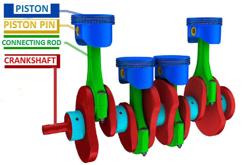
Crank And Piston Mechanism

Crank Mechanism Construction Car Anatomy In Diagram Piston motion equations. the reciprocating motion of a non offset piston connected to a rotating crank through a connecting rod (as would be found in internal combustion engines) can be expressed by equations of motion. this article shows how these equations of motion can be derived using calculus as functions of angle (angle domain) and of. Crank (mechanism) hand crank for a winch on a sailboat commonly referred to as a winch handle. a crank is an arm attached at a right angle to a rotating shaft by which circular motion is imparted to or received from the shaft. when combined with a connecting rod, it can be used to convert circular motion into reciprocating motion, or vice versa.

Piston Crank Mechanism Engineering Mechanics Benchmark Engineering In this example, as the red wheel rotates, the green crank pushes the black and blue connecting rods back and forth, converting the wheel's rotary motion into reciprocal motion. so the red wheel moves round, but the blue rod moves back and forth. the same mechanism could be used the opposite way to drive the wheel from a piston. This mechanism has four parts: the crank is attached to a motor that rotates it. the rod is attached to the crank and the piston at joints that are free to rotate. the guide is fixed in place; its purpose is to make the piston move in a line. the piston is free to move up and down in a line but cannot rotate. Piston slider crank mechanism design equations. displacement of piston slider: angular velocity of connecting rod: linear velocity of piston slider: angular accerelation on connecting rod: piston slider acceleration: where: l = length of connecting rod (in, mm), r = radius of crank (in, mm), x = distance from center of crankshaft a to wrist. Piston crank mechanism | engineering mechanics video lecturesbenchmark engineering laying the foundation for the next generation of engineers. for more vid.

Crankshaft Piston Mechanism Of Engine P1 Piston P2 Piston Pin Piston slider crank mechanism design equations. displacement of piston slider: angular velocity of connecting rod: linear velocity of piston slider: angular accerelation on connecting rod: piston slider acceleration: where: l = length of connecting rod (in, mm), r = radius of crank (in, mm), x = distance from center of crankshaft a to wrist. Piston crank mechanism | engineering mechanics video lecturesbenchmark engineering laying the foundation for the next generation of engineers. for more vid. Demonstration of a crank and piston mechanism, including the tracking of the locus of a point on the connecting rod. the mechanism is shown assembled prior t. The slider crank mechanism shown is driven by the combustion process that occurs above the piston at c. this combustion process generates a time dependent force p (t) which drives the piston down. the motion of the piston drives the crankshaft at a around by way of the connecting rod bc.

Animation Of Single Slider Crank Mechanism Youtube Demonstration of a crank and piston mechanism, including the tracking of the locus of a point on the connecting rod. the mechanism is shown assembled prior t. The slider crank mechanism shown is driven by the combustion process that occurs above the piston at c. this combustion process generates a time dependent force p (t) which drives the piston down. the motion of the piston drives the crankshaft at a around by way of the connecting rod bc.

Comments are closed.