Cooling Tower Wiring Diagram

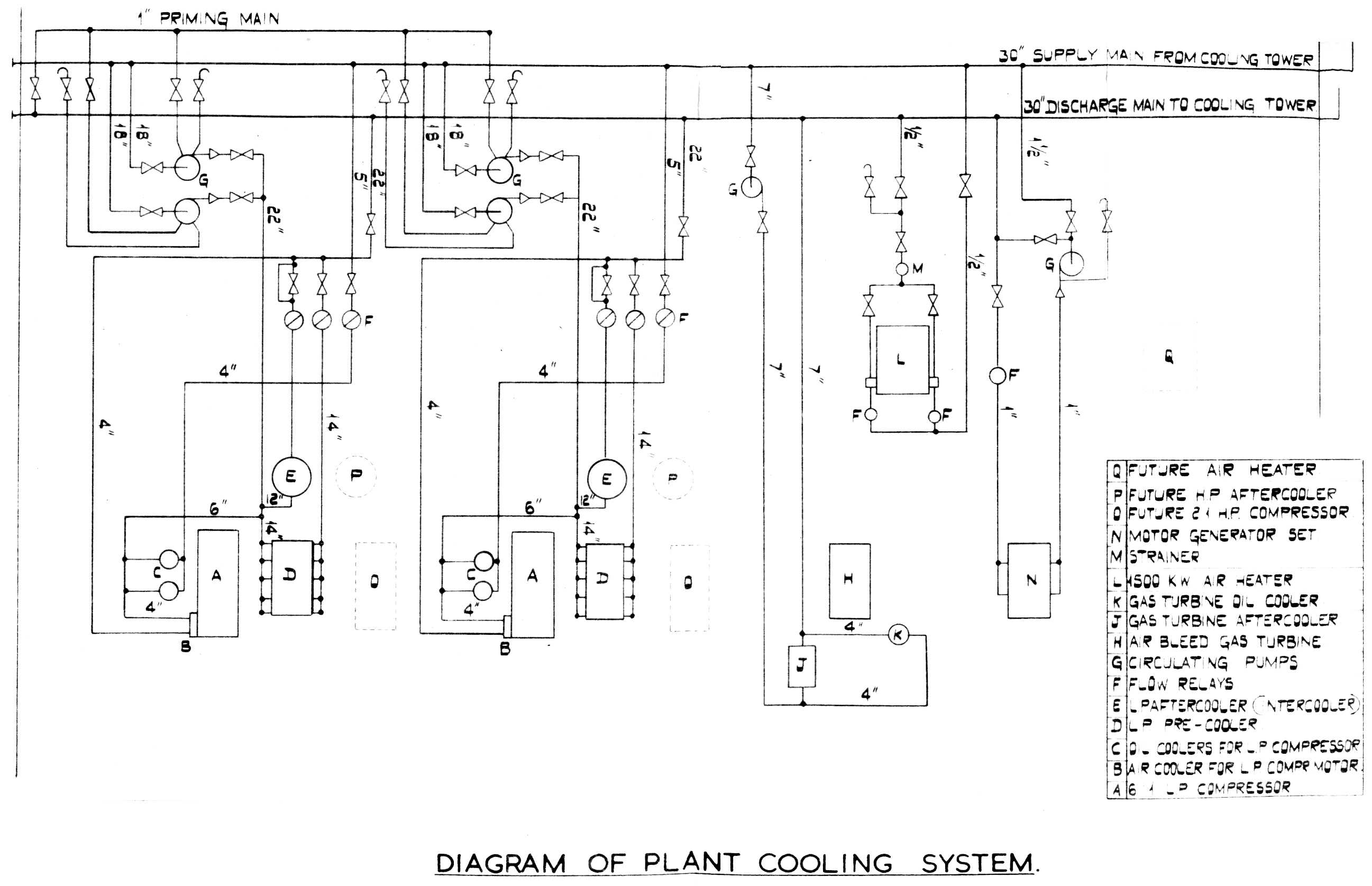
Cooling Tower Piping Schematic Cooling tower | piping layout and diagrams. to allow the cooling towers to operate correctly, in line with the design and efficiently, various systems will need to be connected to allow them to work. depending upon how the towers are installed will mean different configurations would be required. the pipework that is commonly connected to the. User manual 92 1320e. warning. this manual contains vital information for the proper installation and operation of your cooling tower and the basic control system. carefully read the manual before installation or operation of the tower. failure to follow the instructions in this manual may result in substantial personal injury or death.

Evapco Cooling Tower Wiring Diagram Wiring Diagram Pictures A cooling tower flow diagram helps visualise the complex system of the tower and its components. the diagram illustrates the flow of water and air through the tower, as well as the different stages of the cooling process. the cooling tower flow diagram typically begins with the entry of hot water from the industrial process into the tower. Cooling towers are a special type of heat exchanger that allows water and air to come in contact with each other to lower the temperature of the hot water. during this process, small volumes of water evaporate, lowering the temperature of the water that's being circulated throughout the cooling tower. The model 101 series are basic bleed and feed cooling tower controllers. these controllers are also ideal for closed loop systems when configured with reverse setpoint. the basic units are available with digital displays and chemical feed limit timers. other options are flow switches, custom ranges and more. Mount aio control panel away from direct southern exposure to the sun. use the cooling tower as a means to provide shade. run all power circuits through bottom of enclosure connections are located on the user terminal strip typically located top left. refer to door mounted wiring diagram for power and control wiring connections.

Comments are closed.