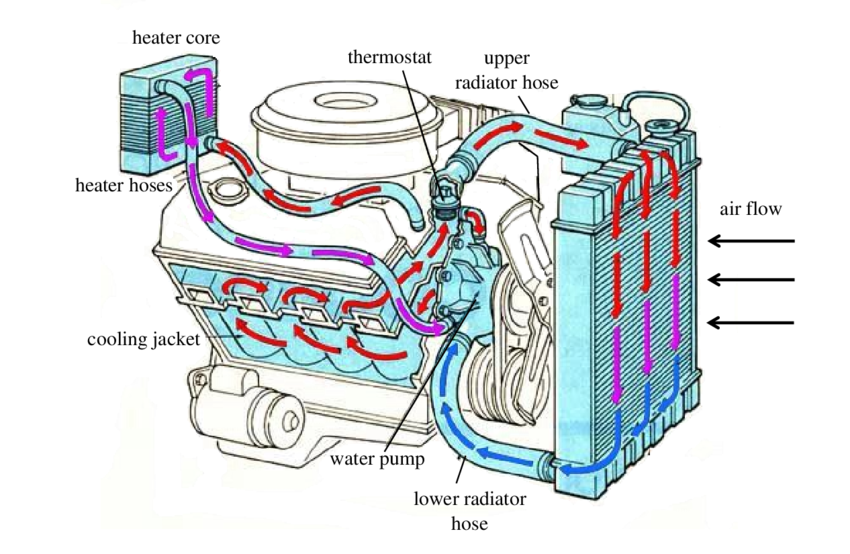
Conventional Cooling Diagram

Schematic Diagram Of A Conventional Cooling System 2 Download Central cooling. if you have a split system, you will have a central cooling and a central heating unit. the central cooling unit works like this: first, warm air blows across the indoor evaporator coil. the heat energy then transfers to the refrigerant inside the coil. this transfer cools the air that passes across the coil. 1] removes extra heat: it is the main function of the engine cooling system to carry away the excess heat generated by the engine. 2] helps to attain optimum temperature faster: the optimum temperature means the temperature at which the engine gives better performance. thus, after starting the engine, it is necessary that the engine should.

Schematic Diagram Of A Conventional Cooling System 2 Download When the clutch input speed is 3000 rad min and the temperature is 100 °c, the output torque is 19.04 n·m, the speed is 2877.2 rad min, and the slip rate is 4.3%. due to the shape memory effect. View. download scientific diagram | conventional cooling system. from publication: thermal energy storage optimization in shopping center buildings | in this research, cooling system optimization. R or rc wire (power) connected to the r power terminal to power the thermostat. w wire (heat), connected to the heating control. g wire (fan) connected to the fan control to operate a blower in your hvac system. y1 wire (cooling) connected to the y terminal compressor refrigerant system. Download scientific diagram | scheme of conventional cooling system (milić, 1991). from publication: simulation modelling of marine diesel engine cooling system | every internal combustion engine.

Schematic Diagram For Conventional Cooling System For Idc Download R or rc wire (power) connected to the r power terminal to power the thermostat. w wire (heat), connected to the heating control. g wire (fan) connected to the fan control to operate a blower in your hvac system. y1 wire (cooling) connected to the y terminal compressor refrigerant system. Download scientific diagram | scheme of conventional cooling system (milić, 1991). from publication: simulation modelling of marine diesel engine cooling system | every internal combustion engine. Moisture content or latent heat of air can be controlled either by condensing the water vapour or by using suitable absorbents as used in desiccant cooling systems. while conventional vcss simultaneously cool and dehumidify the air, a desiccant system only dehumidifies it. If you have a c wire, place it into the c terminal on your wall plate. c wire adapters are available here. let’s look at the g wire. this wire goes to the g terminal on your new thermostat. of the y, y1, and y2 wires, y or y1 go to the y terminal and y2 to the y2 terminal. the o b wire can have many configurations.
3 Block Diagram Of Conventional Cooling System Download Scientific Moisture content or latent heat of air can be controlled either by condensing the water vapour or by using suitable absorbents as used in desiccant cooling systems. while conventional vcss simultaneously cool and dehumidify the air, a desiccant system only dehumidifies it. If you have a c wire, place it into the c terminal on your wall plate. c wire adapters are available here. let’s look at the g wire. this wire goes to the g terminal on your new thermostat. of the y, y1, and y2 wires, y or y1 go to the y terminal and y2 to the y2 terminal. the o b wire can have many configurations.

Conventional Cooling System Download Scientific Diagram

Comments are closed.