Block Diagram Power Electronics Power Block Diagram

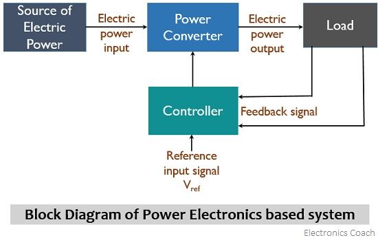
What Is Power Electronics Concept Block Diagram And Applications Of The figure below represents the block diagram of a power electronics based system: as it is clear from the above figure that here we are having a power electronics converter and controller along with some interfacing units. the power converters change one form of electric power into some other form with the use of a power semiconductor device. The major components of a power electronic system are shown in the form of a block diagram. the primary power source might be an alternating current (ac) or direct current (dc) supply system. the output of the power electronic circuit might be changeable dc or alternating current voltage, or it can be variable voltage and frequency.

What Is Power Electronics Power Vs Linear Electronics Uses The complete operation of the system will provide the desired signal at a particular frequency, as shown in the block diagram given below, and it will include several steps: step 1. in power electronic systems, there can be an ac or dc source of electric power. Electronics: solid state electronics devices and their driving circuits. power: static and dynamic requirements for generation, conversion and transmission of power. control: the steady state and dynamic stability of the closed loop system. power electronics may be defined as the application of solid state electronics for the control and. Power electronics: concept, block diagram & applications. power electronics, as the name says is the application of electronics in the field of high power applications. normally, electronics whether analog or digital deal with low power applications confined to a small dc voltage and current. these applications are known to be efficient and. Understanding the block diagram of an smps is essential to grasp its functioning and advantages. the block diagram of an smps consists of several key components: the input rectifier, the filter, the pwm controller, the power mosfet, the transformer, and the output rectifier. each component plays a crucial role in converting the input electrical.

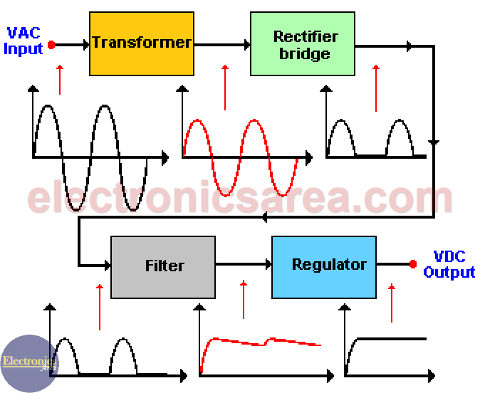
1 Block Diagram Of Power Electronics System Download Scientific Diagramођ Power electronics: concept, block diagram & applications. power electronics, as the name says is the application of electronics in the field of high power applications. normally, electronics whether analog or digital deal with low power applications confined to a small dc voltage and current. these applications are known to be efficient and. Understanding the block diagram of an smps is essential to grasp its functioning and advantages. the block diagram of an smps consists of several key components: the input rectifier, the filter, the pwm controller, the power mosfet, the transformer, and the output rectifier. each component plays a crucial role in converting the input electrical. Block diagram for power supply components. input is 117 volts ac. processes used in a typical power supply are shown below the blocks. the output of the power supply can be dc or ac. the output of this supply is five volts dc. figure 2. regulated dc power supply diagram. (knight electronics) power supply transformers. Power supply block diagram. many electronic circuits need a direct current (dc) voltage source, but what we commonly find are voltage sources of alternating current (ac). in order to achieve a direct current voltage source, the alternating current input must follow a conversion process like the one shown in the power supply block diagram below.

Power Supply Block Diagram Ac Dc Conversion Process Electronics Area Block diagram for power supply components. input is 117 volts ac. processes used in a typical power supply are shown below the blocks. the output of the power supply can be dc or ac. the output of this supply is five volts dc. figure 2. regulated dc power supply diagram. (knight electronics) power supply transformers. Power supply block diagram. many electronic circuits need a direct current (dc) voltage source, but what we commonly find are voltage sources of alternating current (ac). in order to achieve a direct current voltage source, the alternating current input must follow a conversion process like the one shown in the power supply block diagram below.

Comments are closed.