Block Diagram For Power Supply

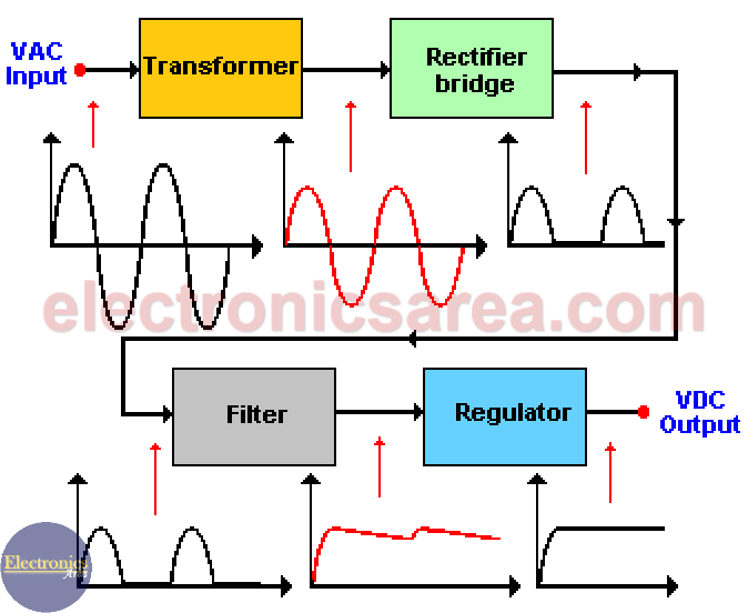
Power Supply Block Diagram Ac Dc Conversion Process Electronics Area The image shows the main components of a basic power supply diagram and the waveforms at the beginning (ac input), at the end (dc output) and between blocks. input signal which goes to the transformer primary winding is a sine wave and its amplitude depends on the country’s electric distribution system (110 220 vac or other). This article provides a detailed explanation of the block diagram of a switched mode power supply (smps), including its different components and their functions. it covers the working principle of an smps and the benefits it offers in terms of efficiency and size reduction. discover how an smps converts high voltage ac power into low voltage dc power through the use of rectification.

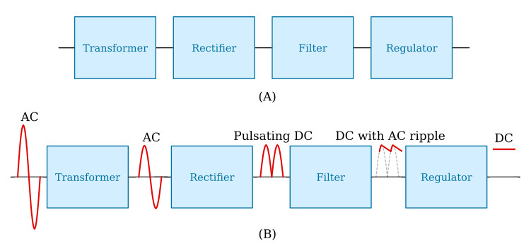
Block Diagram Of Power Supply Circuit See figure 2 for typical commercial power supply components. figure 1. block diagram for power supply components. input is 117 volts ac. processes used in a typical power supply are shown below the blocks. the output of the power supply can be dc or ac. the output of this supply is five volts dc. figure 2. regulated dc power supply diagram. Figure 2: linear ac dc power supply block diagram. traditional linear ac dc power supply design has evolved over the years, improving in terms of efficiency, power range, and size — but this design has some significant flaws that limit its integration. a huge limitation in a linear ac dc power supply is the size of the transformer. A power supply block diagram is a representation of the various components and their interconnectedness in a power supply system. the power supply is responsible for transforming electrical energy from an input source, such as a wall outlet, into a form that can be used to power electronic devices. it is an essential component in any electronic. The block diagram in figure 1 is representative of many ac dc or dc dc power supplies. the difference in the block diagram between ac dc versus dc dc input supplies is the diode bridge rectifier. a rectifier circuit (diodes d1, d2, d3, d4) is required in ac dc power supplies and is not needed for dc dc power supplies, otherwise the power supply.

Block Diagram Of Power Supply Unit A power supply block diagram is a representation of the various components and their interconnectedness in a power supply system. the power supply is responsible for transforming electrical energy from an input source, such as a wall outlet, into a form that can be used to power electronic devices. it is an essential component in any electronic. The block diagram in figure 1 is representative of many ac dc or dc dc power supplies. the difference in the block diagram between ac dc versus dc dc input supplies is the diode bridge rectifier. a rectifier circuit (diodes d1, d2, d3, d4) is required in ac dc power supplies and is not needed for dc dc power supplies, otherwise the power supply. A switch mode power supply (smps) is a type of power supply that uses a high frequency switching regulator to convert electrical power efficiently. the block diagram of a switch mode power supply typically consists of several key components. input stage: the input stage of an smps includes an ac input filter, rectifier, and a bulk capacitor. Figure 2: linear ac dc power supply block diagram traditional linear ac dc power supply design has evolved over the years, improving in terms of efficiency, power range, and size — but this design has some significant flaws that limit its integration. a huge limitation in a linear ac dc power supply is the size of the transformer.

Comments are closed.