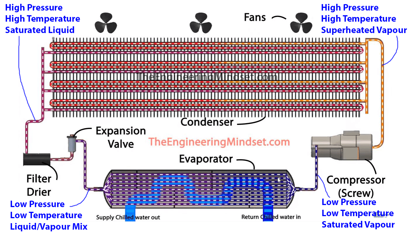
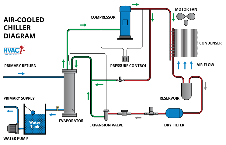
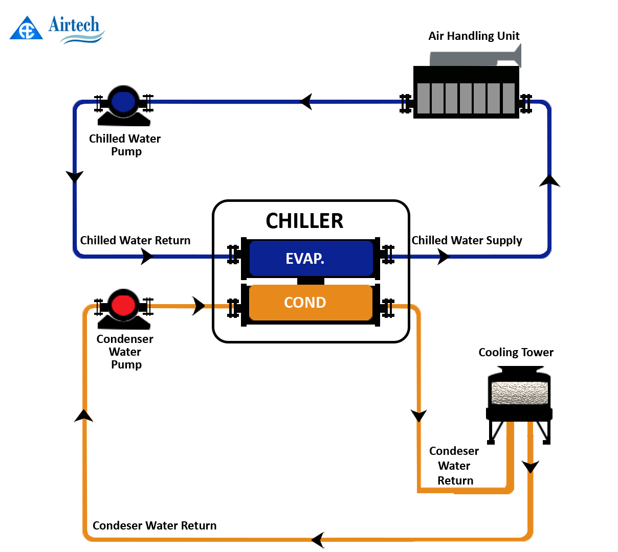
Air Cooled Screw Chiller Schematic Diagram

Air Cooled Chiller Schematic Diagram Rt = rotary chiller digit 3 unit type a= air cooled digit 4 development sequence c = development sequence digits 5, 6 and 7 nominal capacity 120 = 120 nominal tons 130 = 130 nominal tons 140 = 140 nominal tons 155 = 155 nominal tons 170 = 170 nominal tons 185 = 185 nominal tons 200 = 200 nominal tons 225 = 225 nominal tons. Condensers are easy to clean shell and through tube type. standard configuration is 2 passes. the unit has completely assembled independent exchangers, one per circuit. each heat recovery condenser has integrally finned high efficiency seamless copper tubes, roll expanded into heavy carbon steel tube sheets.

Air Cooled Chiller System Schematic Diagram Acr = air cooled screw chiller digit 4 — series c = series c digit 5, 6, 7 — nominal tonnage 150 = 150 tons 165 = 165 tons 180 = 180 tons 200 = 200 tons 225 = 225 tons 250 = 250 tons 275 = 275 tons 300 = 300 tons 330 = 330 tons 375 = 375 tons 380 = 380 tons 440 = 440 tons 450 = 450 tons 500 = 500 tons 550 = 550 tons digit 8 — compressor type. Era: air cooled condensing unit eww: water cooled packaged water chiller ewl: remote condenser water chiller ewa: air cooled chiller, cooling only ewy: air cooled chiller, heat pump ewc: air cooled chiller, cooling only with centrifugal fan ewt: air cooled chiller, cooling only with heat recovery refrigerant d: r 134a p: r 407c q: r 410a. This manual provides setup, operating, troubleshooting and maintenance information for the daikin air cooled chillers with screw compressor (no vfd) with 1, 2 and 3 circuits using microtech controller. danger dangers indicate a hazardous situation which will result in death or serious injury if not avoided. warning. To change the filter drier, close the manual liquid line shutoff valve, pump the unit down by opening the switches q1, q2 (on off switches compressors) in “off” position. move the on off switch unit q0 to the “off” position. close the suction line valve. remove and replace the filter drier.

Air Cooled Chiller Schematic Di This manual provides setup, operating, troubleshooting and maintenance information for the daikin air cooled chillers with screw compressor (no vfd) with 1, 2 and 3 circuits using microtech controller. danger dangers indicate a hazardous situation which will result in death or serious injury if not avoided. warning. To change the filter drier, close the manual liquid line shutoff valve, pump the unit down by opening the switches q1, q2 (on off switches compressors) in “off” position. move the on off switch unit q0 to the “off” position. close the suction line valve. remove and replace the filter drier. Air cooled screw liquid chillers new release form 201.18 nm3 (300) millennium® ycas air cooled liquid chiller ycas 250, 270, 300, 330 (3 compressor) ycas 360, 400, 440 (4 compressor) style f 60 hz 00258vip ycas 3 system eproms microprocessor board 031 01798 002 ycas 4 system eproms microprocessor board i o board #2 eprom 031 01798 002 031. Sintesis™ air cooled chillers model rtaf installation, operation, and maintenance april 2022 rtaf svx001k en sintesis™ chillers are part of the ingersoll rand ecowise™ portfolio of products that are designed to lower the environmental impact with next generation, low global warming potential (gwp) refrigerants and high efficiency operation.

Comments are closed.