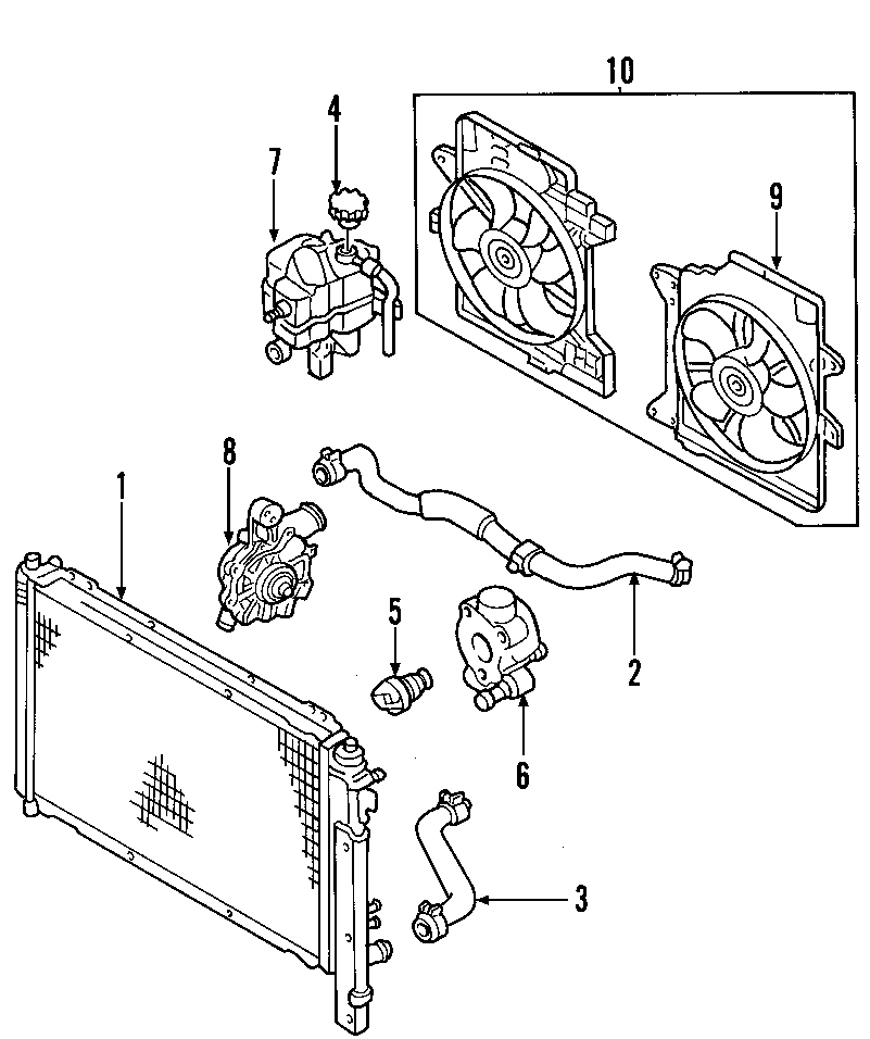
82 4hp Mariner Cooling System Diagram

Mercury Mariner Radiator Coolant Hose Upper Lower 9l8z8286b The cooling system in a mercury outboard motor is a critical component that plays a vital role in maintaining the engine’s optimal operating temperature. it is essential for the proper functioning and longevity of the motor. without a properly functioning cooling system, the engine can overheat, leading to severe damage and potential breakdowns. An opened ended hose, or a hose leading to an outlet nipple in the casing would be what you are looking for if there is one. there should be some water, droplets or a mist being blown out of the exhaust back pressure relief ports. if the motor has been idle for sometime a replacement waterpump impeller would be wise.

Marine Engine Cooling System Diagram The cooling system on an outboard is a very simple and compact application. water is inducted through the lower unit by a water pump impeller, and then forced upward to circulate throughout the powerhead, and eventually exits through the exhaust system. there are a couple of things pertaining to the outboard cooling system that need regular. I just bought an old mercury 4hp 2 cylinder (internal fuel tank) outboard at a garage sale and i went about changing the impeller. my question is: where is the water outlet (pee hole). i can not find it anywhere. i do not want to fire this thing up and not know whether or not the cooling system is working. any help is appreciated,. The ignition system is crucial for starting the engine and maintaining its smooth operation. in the parts diagram, the ignition system components are often represented by symbols or labeled boxes. 4. cooling system. the cooling system in a mariner outboard engine helps regulate the engine temperature and prevent overheating. 5. page 277 jet drive installation 1. grease the drive shaft, shear key, and impeller bore. place the plastic sleeve (a) in side the impeller (b) and install impeller, shear key (c), shims (d) nut retainer (e), and impeller nut (f). turn the nut tight on the shaft to remove any play between the impeller and shaft.

Comments are closed.