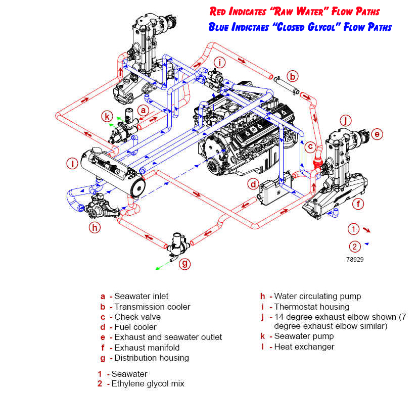
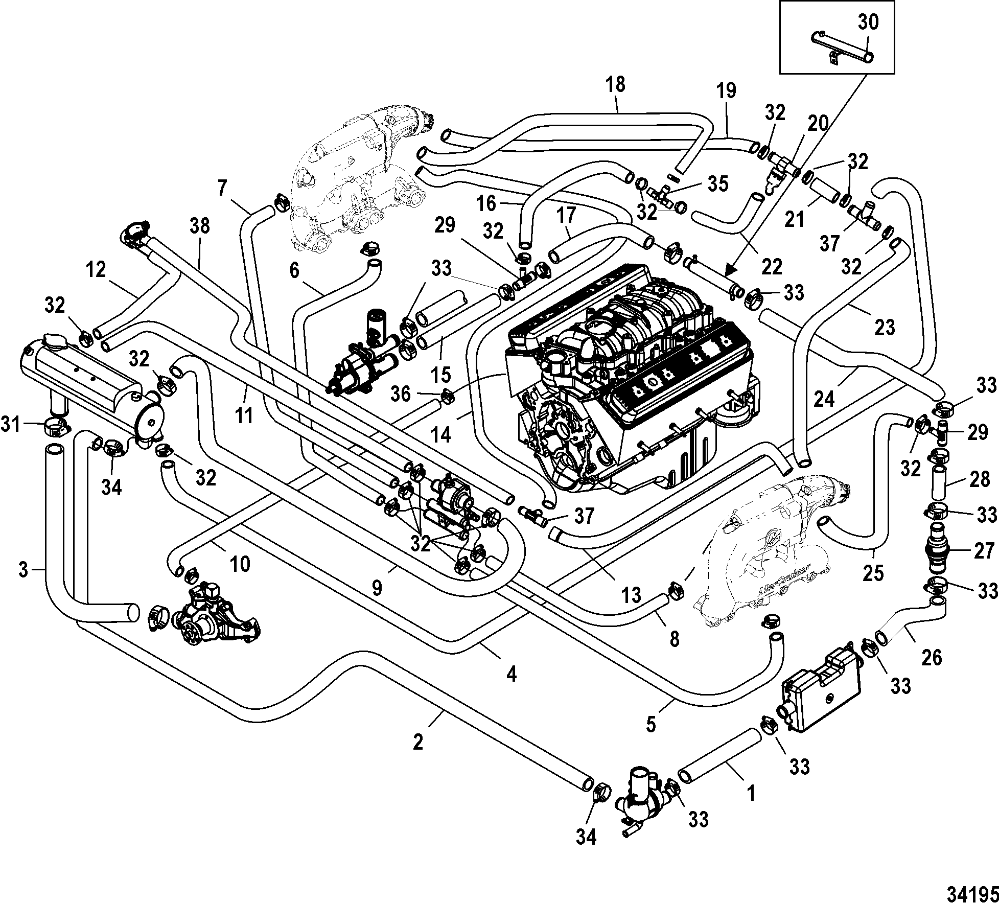
7 4 Mercruiser Engine Cooling Water Line Diagram

Diagram 7 4 Mercruiser Engine Cooling Diagram Mydiagram O The cooling system in a mercruiser engine consists of several components, including the water pump, thermostat, heat exchanger, and circulating pump. understanding how these components work together to ensure proper coolant flow is crucial for troubleshooting and diagnosing potential problems. the flow of coolant begins with the water pump. 916. 993. 1012. advertisement. mercury mercruiser mie 7.4l mpi pdf user manuals. view online or download mercury mercruiser mie 7.4l mpi service manual.

Mercruiser 7 4 Cooling System Diagram Huzaifaadley 7.4 l bravo iii. when ever i drain antifreeze from my engine i attach a large funnel to a piece of hose and rout the hose out the transom drain hole. put a big container under there and catch most of the anti freeze for proper disposal. when refilling remember to open the bleeder valve to get rid of trapped air. Numbers on the heads of the met ric bolts and on the surfaces of metric nuts indicate their strength. american bolts use radial lines for this purpose, while most american nuts do not have strength markings. page 4 models covered in this manual gen. vi engines sterndrive (mcm) model serial number mcm 454 mag mpi 0l010029 & up mcm 502 mag mpi. After break in period. ndations should be considered;use a propeller that allows the engine to operate at or near the top of the maximum rpm range (see “specifications” section) when at full th. ttle with a normal boat load.operation at 3 4 throttle s. tting or lower is recommended. refrain from prolonged operation. Standard cooling system for mercruiser (7.4 l mpi bravo gen vi l29) engine start over different model > different engine section > standard cooling system reference numbers in this diagram can be found in a light blue row below — scroll down to order.

Mercruiser Fresh Water Cooling System Diagram Headcontrolsystem After break in period. ndations should be considered;use a propeller that allows the engine to operate at or near the top of the maximum rpm range (see “specifications” section) when at full th. ttle with a normal boat load.operation at 3 4 throttle s. tting or lower is recommended. refrain from prolonged operation. Standard cooling system for mercruiser (7.4 l mpi bravo gen vi l29) engine start over different model > different engine section > standard cooling system reference numbers in this diagram can be found in a light blue row below — scroll down to order. Crusader model 454 454 c.i.d 7.4l raw water cooling components. gen v engines with one piece main seal. carbureted engines with serial numbers 88710& up. ref #. View and download mercruiser 454 magnum manual online. 7.4l 8.2l. 454 magnum engine pdf manual download. also for: 502 magnum.

Coolant Flow Problems With 7 3 Powerstroke Water Pump Solved Crusader model 454 454 c.i.d 7.4l raw water cooling components. gen v engines with one piece main seal. carbureted engines with serial numbers 88710& up. ref #. View and download mercruiser 454 magnum manual online. 7.4l 8.2l. 454 magnum engine pdf manual download. also for: 502 magnum.

Comments are closed.