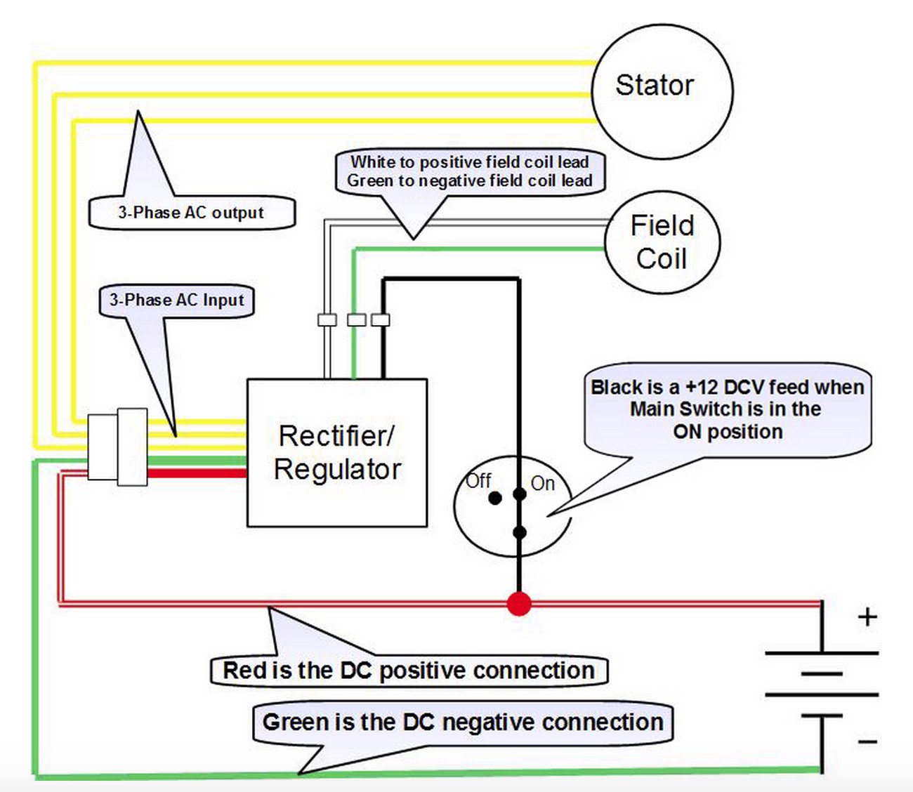
12v 3 Phase Motorcycle Regulator Rectifier Circuit Wiring Diagram

12v 3 Phase Motorcycle Regulator Rectifier Circuit Wiring Diagram Generally, you need to find a zener diode so that the whole scheme gave the needed voltage. for a start try to understand what is the correct voltage. if an ordinary battery is acid, its rate of charge lays within 13.8 14.5 v. if the battery is gel, the rate is 14.5 15.5 v. different sources say different. The 3 phase regulator rectifier wiring diagram is an essential component in the electrical system of a three phase motorcycle or vehicle. it plays a crucial role in converting the ac voltage generated by the motorcycle’s alternator into dc voltage, which is necessary to charge the battery and power the motorcycle’s electrical system. a.

12v 3 Phase Motorcycle Regulator Rectifier Circuit Wiring Diagram 5 motorcycle voltage regulator using scrs. 5.1 circuit diagram. 5.2 circuit operation. 5.3 using two bridge rectifiers. 5.4 bridge rectifier. 5.5 3 phase rectifier. 5.6 bridge rectifier. 6 mosfet full wave shunt regulator circuit. 7 how a shunt regulator works. Most motorcycle regulator rectifier wiring diagrams use color coding to make understanding the diagram simpler. each wire is represented by a different color in the diagram, making it easier to spot the connections between each component and wire. depending on the type of motorcycle, the color coding may differ, but the basics are usually the same. All wiring instructions are as the same as the single phase apart from the following; the should be 4 wires connected to the rectifier. the white green, green black and green yellow connect from the stator to the rectifier. connect the 3 stator wires to the 3 yellow wires on the power module. converting a 6v, 3 wire stator to 12v. Step by step guide to wiring a motorcycle regulator rectifier. wiring a motorcycle regulator rectifier can seem like a complex task, but it can be broken down into a step by step process. by following these steps and using a diagram as a guide, you can successfully wire a regulator rectifier to your motorcycle. step 1: gather the necessary.

12v 3 Phase Motorcycle Regulator Rectifier Circuit Wiring Diagram All wiring instructions are as the same as the single phase apart from the following; the should be 4 wires connected to the rectifier. the white green, green black and green yellow connect from the stator to the rectifier. connect the 3 stator wires to the 3 yellow wires on the power module. converting a 6v, 3 wire stator to 12v. Step by step guide to wiring a motorcycle regulator rectifier. wiring a motorcycle regulator rectifier can seem like a complex task, but it can be broken down into a step by step process. by following these steps and using a diagram as a guide, you can successfully wire a regulator rectifier to your motorcycle. step 1: gather the necessary. Revivalcycles in this episode alan and alec discuss regulator rectifiers, what they are, what they do, why you need one, and which one do you need. 3) 4 pin regulator (a): this type may be found on some motorcycles. in this system, both the ends of the winding go to the rectifier section which converts ac to dc voltage and then the regulator section regulates to 14.4v as discussed above. 4) 4 pin regulator (b): this is the most common type found on motorcycles with single phase winding.

Comments are closed.